Floating Grid Power Quality Case Study: How Major Cement Plant Saved ₹10 Million with InPhase AHF
Cement and steel industries operating with captive power plants face unique power quality challenges, particularly in floating grid conditions where maintaining stable power factor becomes critical. This detailed case study examines how Major Cement Industries plant overcame severe power factor penalties and achieved remarkable cost savings through strategic implementation of InPhase Active Harmonic Filter technology.
The Floating Grid Challenge in Heavy Industries
Understanding Floating Grid Operations
Most cement and steel industries establish captive power plants (CPP) to reduce energy costs and improve reliability compared to utility grid supply. In floating grid configuration, the majority of active power (kW) and steady reactive power (kVAr) demands are supplied by the CPP, while dynamic reactive power requirements are drawn from the utility grid.
This operational approach creates significant challenges:
- Wide variations in lagging and leading power factor with the grid under light load conditions
- Difficulty maintaining minimum power factor requirements (typically 0.9 lagging)
- Substantial utility penalties for non-compliance
- Equipment stress from rapid reactive power fluctuations
Technical Limitations of Conventional Solutions
Traditional Static Var Compensation (SVC) systems become economically viable only for capacities above 50-100 MVAr, making them unsuitable for floating grid applications typically requiring less than 10-25 MVAr compensation. Conventional capacitor-based compensators cannot meet the fast inductive or capacitive power exchange demands, necessitating IGBT-based active solutions.
Pre-Installation Challenges
The plant experienced severe power quality issues that resulted in substantial financial penalties:
Power Factor Penalty Analysis
Between January 2017 and March 2018, Major Cement Industries are paid approximately ₹10 million in power factor penalties due to inability to maintain the minimum 0.9 lagging power factor requirement.
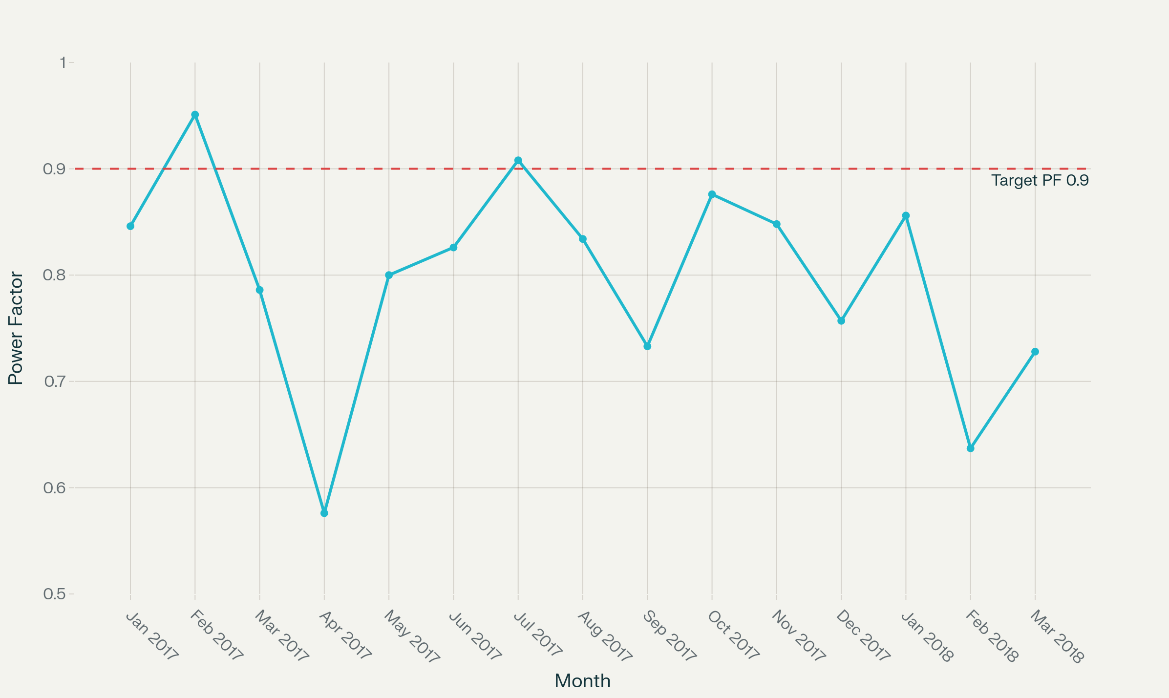
The monthly penalty breakdown revealed: 
- Highest penalty: ₹1,310,139 (February 2018, PF 0.637)
- Lowest power factor: 0.576 (April 2017)
- Only two months achieved penalty-free operation
- Average power factor: 0.840 (well below 0.9 requirement)
Reactive Power Variations
The facility experienced extreme reactive power fluctuations ranging from +3,000 kVAr (inductive) to -3,000 kVAr (capacitive), making conventional compensation methods inadequate.
InPhase Power Technologies Solution
Vendor Selection Criteria
Major Cement Industries implemented a rigorous technical evaluation process focusing on:
- IGBT-based Active Technology: Fast response capability for dynamic compensation
- 3-Level Topology: Superior performance under wide voltage variations (-10% to +15%)
- High Efficiency: Greater than 98% efficiency requirement
- Network Voltage: 690V system to reduce losses and installation costs
- Line Capacitance Compensation: Ability to compensate for 22.5km transmission line capacitance
- Local Technical Support: Rapid deployment and ongoing maintenance capability
Implemented Solution Architecture
InPhase installed a comprehensive 1000 KVAR active compensation system comprising:
- Two 400A, 690V Active Harmonic Filters: Parallel-connected configuration
- Step-down Transformer: 6.6kV/690V, 2.5MVA capacity for future expansion
- 3-Level IGBT Technology: Superior waveform quality and reduced losses
- Integrated Capacitor Bank Control (ICBC): Smart coordination of existing passive capacitors
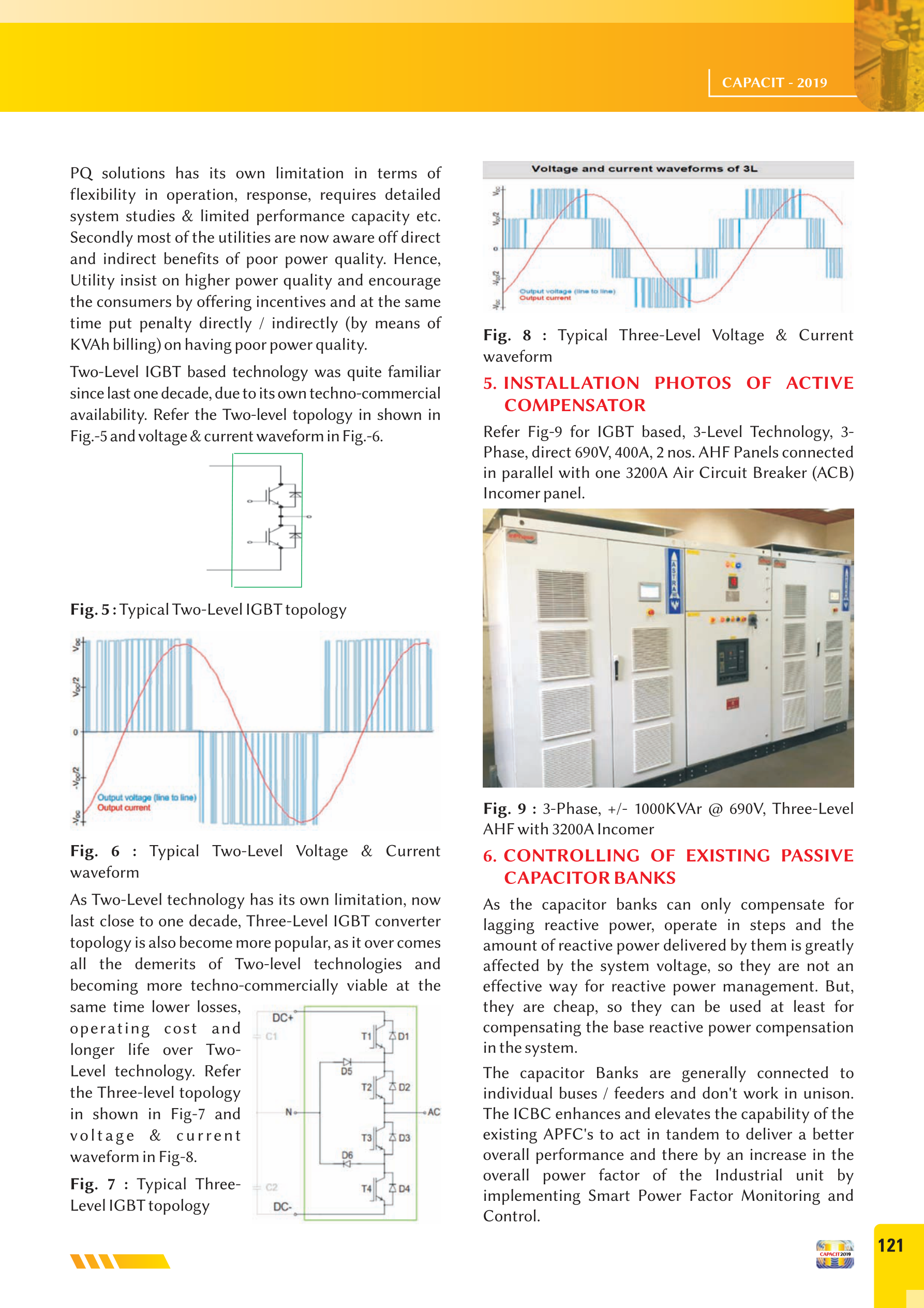
Technical Advantages of 3-Level Technology
The implemented 3-level IGBT topology provides significant benefits over conventional 2-level systems:
- Reduced Voltage Stress: Lower stress on switching components
- Improved Efficiency: Minimal switching losses and heat generation
- Better Harmonic Performance: Superior output waveform quality
- Enhanced Reliability: Longer operational life and reduced maintenance
Performance Results and Financial Impact
Immediate Power Factor Improvement
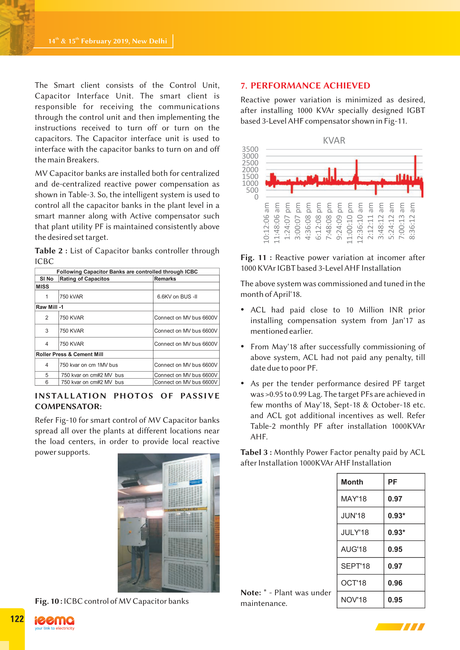
Following commissioning in April 2018, Major Cement Industry achieved dramatic improvements in power factor performance:
Post-Installation Monthly Results:
- May 2018: 0.97 PF (achieved incentive)
- August 2018: 0.95 PF (target achieved)
- September 2018: 0.97 PF (incentive earned)
- October 2018: 0.96 PF (target exceeded)
- November 2018: 0.95 PF (compliant)
Reactive Power Stabilization
The AHF installation dramatically reduced reactive power variations, providing stable grid interface operation.
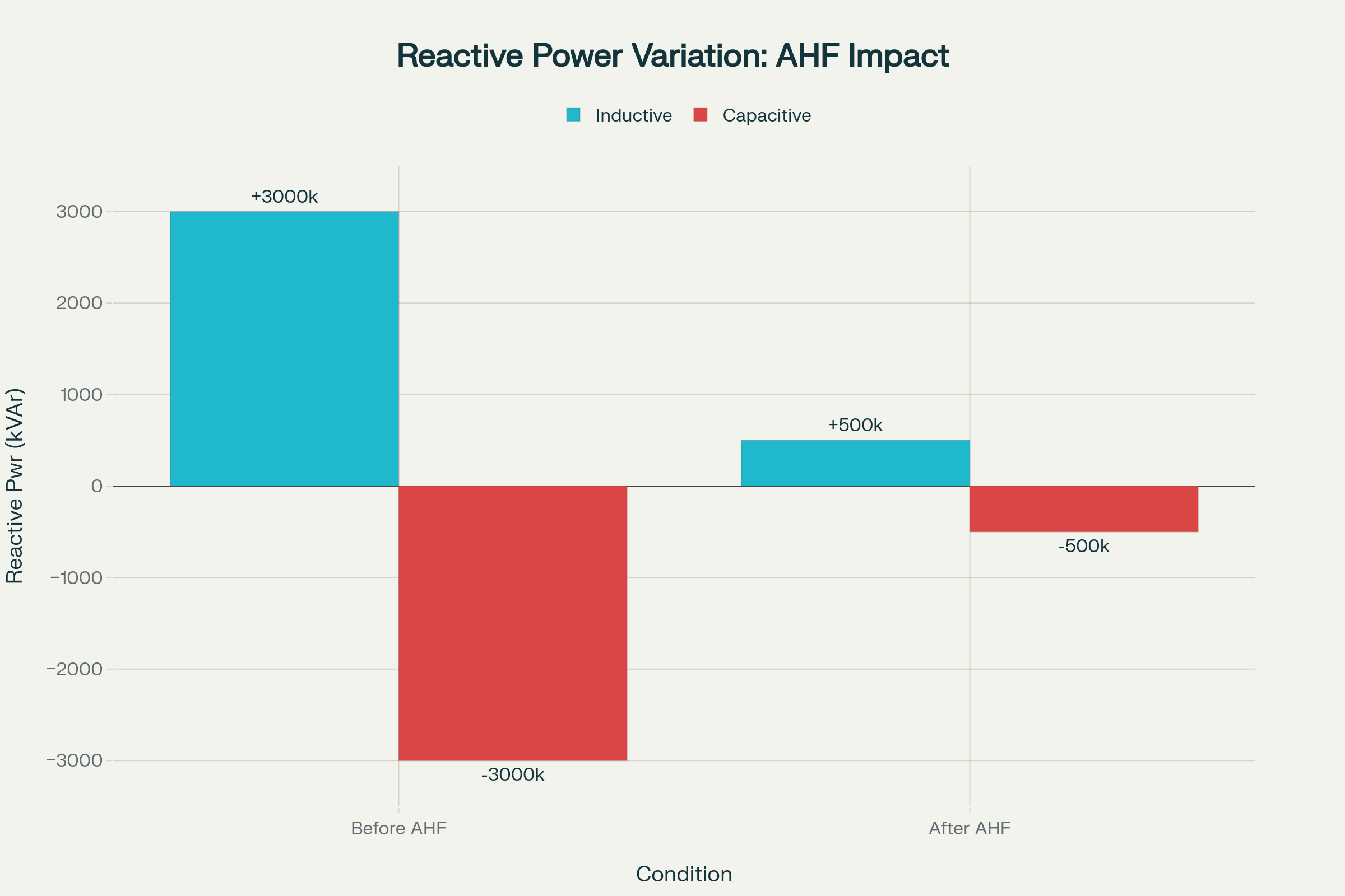
Reactive Power Variation Comparison – Before vs After AHF Installation
Key Improvements:
- Reactive power variation reduced from ±3,000 kVAr to ±500 kVAr
- Elimination of rapid fluctuations causing grid instability
- Smooth CPP operation without power factor stress
- Consistent utility grid interface performance
Economic Benefits Analysis
Direct Cost Savings
- Penalty Elimination: Zero power factor penalties from May 2018 onwards
- Annual Savings: Minimum ₹10 million annually based on historical penalty data
- Incentive Earnings: Additional utility incentives for exceeding 0.95 power factor
- Payback Period: Less than 12 months including system losses consideration
Operational Improvements
- Equipment Protection: Reduced stress on transformers, motors, and cables
- System Efficiency: Minimized losses in distribution infrastructure
- Process Stability: Improved power plant operation with reduced variations
- Maintenance Reduction: Lower maintenance requirements due to stable operation
Integrated Capacitor Bank Control System
Smart Coordination Strategy
The ICBC system enhanced overall performance by intelligently coordinating existing capacitor banks throughout the facility :
Controlled Capacitor Banks:
- Main Incoming Substation (MISS): 750 kVAr
- Raw Mill-1: 750 kVAr
- Roller Press & Cement Mill: Multiple 750 kVAr units
- Distributed MV capacitor banks across production areas
Benefits of Integrated Control
- Unified Operation: Coordinated response to varying load conditions
- Optimized Compensation: Balanced active and passive compensation
- Reduced Investment: Maximum utilization of existing infrastructure
- Enhanced Reliability: Redundant compensation capability
Technical Specifications and Performance
System Efficiency Metrics
- AHF Efficiency: >98% at rated load
- Transformer Efficiency: >99.35% for 2500kVA step-down unit
- Overall System Losses: <2% of rated power
- Loss Compensation: Upstream cable and transformer loss reduction
Operational Characteristics
- Response Time: Instantaneous compensation for dynamic loads
- Voltage Range: -10% to +15% operating capability
- Frequency Tolerance: ±5% frequency variation handling
- Environmental Conditions: Suitable for harsh industrial environments
Lessons Learned and Best Practices
Critical Success Factors
- Comprehensive System Study: Detailed analysis of load patterns and grid interface requirements
- Technology Selection: Choosing appropriate 3-level IGBT technology for superior performance
- Future-Ready Design: Installing higher-capacity transformer for potential expansion
- Integrated Approach: Coordinating active and passive compensation elements
- Local Support: Ensuring rapid deployment and ongoing technical assistance
Industry Applicability
This solution approach is particularly beneficial for:
- Cement Manufacturing: High power demand with variable load patterns
- Steel Production: Arc furnace and rolling mill applications
- Process Industries: Continuous manufacturing with CPP integration
- Mining Operations: Remote locations with captive power generation
Return on Investment Analysis
Financial Metrics
- Initial Investment: 1000 kVAr AHF system plus installation
- Annual Savings: ₹10 million minimum in penalty avoidance
- Additional Benefits: Equipment life extension and maintenance reduction
- Payback Period: 10-12 months
Long-term Value Creation
- Regulatory Compliance: Consistent adherence to utility power factor requirements
- Operational Excellence: Improved process stability and equipment reliability
- Risk Mitigation: Protection against future utility penalty increases
- Scalability: Foundation for additional capacity expansion
Conclusion
This cement facility case study demonstrates that floating grid power quality challenges can be effectively addressed through properly engineered active compensation solutions. The implementation of InPhase 3-level IGBT-based Active Harmonic Filter technology delivered:
- Complete penalty elimination saving ₹10 million annually
- Power factor improvement from 0.840 to consistent >0.95 performance
- System stability enhancement through reactive power variation control
- Rapid payback achievement in less than 12 months
- Operational reliability improvement across the entire facility
This successful deployment establishes a proven methodology for addressing similar power quality challenges in heavy industries operating with captive power plants in floating grid configurations. The combination of advanced 3-level IGBT technology, intelligent capacitor bank coordination, and comprehensive system integration provides a cost-effective solution for maintaining regulatory compliance while achieving significant operational improvements.
For cement, steel, and other process industries facing similar floating grid power quality challenges, this case study provides a roadmap for implementing effective, economically viable solutions that deliver immediate and long-term value.