
How Static VAR Generator Is Replacing Capacitor Banks for Reactive Power Compensation
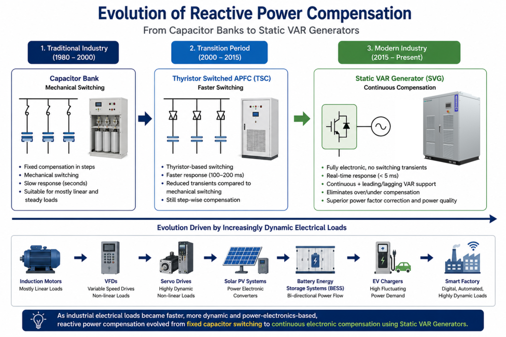
How Static VAR Generator is replacing capacitor banks has become one of the most important discussions in modern industrial power systems. For more than five decades, capacitor banks have been the preferred solution for reactive power compensation in industrial electrical systems. Their simple operating principle, relatively low installation cost and proven reliability made them an effective choice for improving power factor in facilities dominated by induction motors, transformers and other linear electrical loads. For many industries, conventional Automatic Power Factor Correction (APFC) panels provided an economical way to reduce reactive power demand, improve electrical efficiency and avoid utility power factor penalties.
However, the operating characteristics of modern electrical systems have changed dramatically. Today’s industrial facilities increasingly rely on Variable Frequency Drives (VFDs), servo motors, robotics, UPS systems, renewable energy converters, Battery Energy Storage Systems (BESS) and electric vehicle charging infrastructure. Unlike traditional loads, these power-electronic-based systems introduce rapidly changing reactive power demand, harmonic distortion and dynamic operating conditions that conventional capacitor banks were never designed to manage effectively.
As a result, the discussion surrounding Static VAR Generator vs Capacitor Bank has become increasingly important. While capacitor banks remain suitable for stable electrical systems with relatively constant reactive power demand, many modern industrial applications require faster, more accurate and continuously variable compensation to maintain high power quality and stable electrical performance.
A Static VAR Generator (SVG) addresses these challenges by replacing discrete capacitor switching with fully controlled power electronic converters capable of generating or absorbing reactive current in real time. Instead of compensating reactive power in fixed steps, SVGs continuously adjust their output according to instantaneous system requirements, enabling precise dynamic reactive power compensation, improved voltage stability and near-unity power factor even under rapidly changing load conditions.
This article explains how Static VAR Generator technology is replacing conventional capacitor banks, examines the engineering limitations of capacitor-based compensation and demonstrates why SVGs have become the preferred solution for modern industrial power quality applications.
Why Capacitor Banks Dominated Industrial Power Systems
Before the emergence of modern power electronic compensation systems, capacitor banks were the most practical and economical solution for reactive power compensation in industrial electrical networks. For decades, industries such as cement, steel, textile, paper, water treatment and manufacturing relied on Automatic Power Factor Correction (APFC) panels to improve power factor correction, reduce reactive power demand and avoid utility penalty charges.
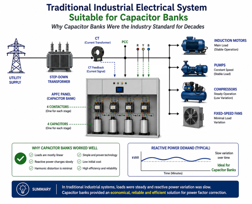
The widespread adoption of capacitor banks was primarily driven by the nature of traditional industrial loads. Most electrical equipment consisted of induction motors, transformers, pumps, compressors and fixed-speed fans operating under relatively stable loading conditions. Since the reactive power demand changed slowly, capacitor banks could effectively compensate for lagging reactive power by switching capacitor stages ON or OFF through contactors or thyristors.
Conventional APFC panels monitored the system power factor using Current Transformers (CTs) and automatically switched capacitor stages whenever the measured power factor dropped below the preset value. Because load variations were generally slow, switching delays of a few seconds had little impact on overall electrical system performance.
Capacitor banks also offered several practical advantages that contributed to their long-standing popularity:
- Simple operating principle with proven reliability
- Low initial investment cost
- High operating efficiency with minimal losses
- Easy installation and maintenance
- Suitable for stable and predictable industrial loads
- Effective reduction of utility power factor penalties
For many years, these advantages made capacitor banks the preferred choice for industrial power quality improvement. In facilities where electrical loads remained relatively constant and harmonic distortion was minimal, capacitor banks provided a cost-effective method of improving power factor without requiring complex power electronic converters.
However, this success was largely based on the characteristics of traditional electrical systems. As industrial processes evolved and nonlinear, rapidly changing loads became increasingly common, the operating assumptions on which capacitor banks were designed gradually became less valid. These changing conditions ultimately paved the way for the adoption of Static VAR Generators capable of delivering continuous dynamic reactive power compensation.
Engineering Perspective
Capacitor banks became the industry standard because they matched the electrical characteristics of traditional industrial facilities. When reactive power demand changed slowly and harmonic distortion was low, step-switched capacitor compensation provided an economical and reliable solution. The transition toward Static VAR Generators did not occur because capacitor banks were ineffective, but because modern electrical systems now require faster, more accurate and continuously adaptive reactive power compensation than conventional capacitor-based systems can provide.
Industry Perspective
As industrial electrical systems evolved beyond the capabilities of conventional capacitor banks, companies such as InPhase Power Technologies began developing advanced Static VAR Generator solutions to meet the growing demand for fast, accurate and dynamic reactive power compensation. By combining intelligent digital control, high-performance power electronics and modular converter technology, modern SVG solutions enable industries to achieve superior power factor correction and improved power quality under rapidly changing operating conditions.
What Changed in Modern Electrical Systems?
For several decades, conventional capacitor banks successfully met the reactive power compensation requirements of industrial facilities because electrical loads remained relatively predictable. However, the rapid advancement of industrial automation, digital manufacturing and power electronic technologies has fundamentally transformed the operating characteristics of modern electrical systems.
Today’s industries are no longer dominated by fixed-speed induction motors and constant-load equipment. Instead, electrical networks increasingly include Variable Frequency Drives (VFDs), servo drives, robotics, UPS systems, renewable energy inverters, Battery Energy Storage Systems (BESS) and electric vehicle charging infrastructure. These nonlinear loads continuously vary their power consumption, resulting in rapidly changing reactive power demand that conventional step-switched capacitor banks struggle to compensate accurately.
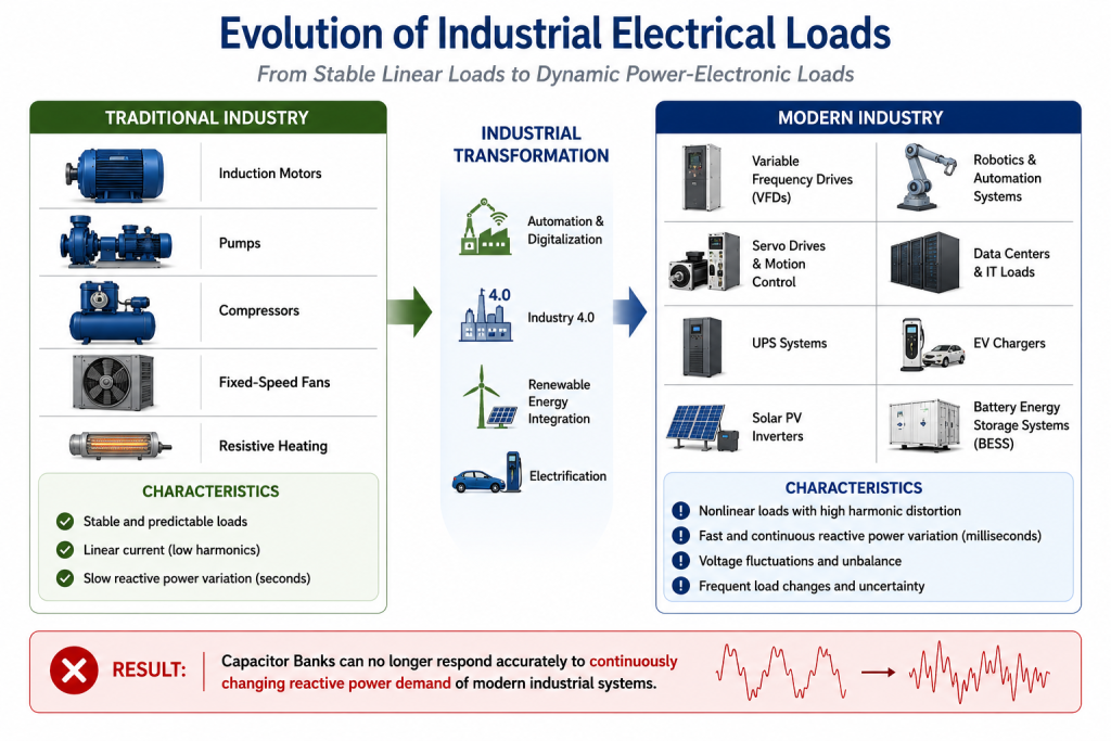
Unlike traditional motor loads, modern power electronic converters switch at high frequencies and draw non-sinusoidal currents from the supply. This not only causes frequent fluctuations in reactive power demand but also introduces harmonic distortion, voltage fluctuations and other power quality issues that were relatively uncommon in conventional industrial power systems.
As industrial processes become more automated, production lines operate at varying speeds, motors accelerate and decelerate continuously, renewable energy output changes with environmental conditions and electric vehicle charging loads fluctuate unpredictably. Consequently, the reactive power required by the electrical system can change within milliseconds rather than seconds.
These rapidly changing operating conditions expose the inherent limitations of conventional capacitor banks, which compensate reactive power in fixed stages and require switching delays between capacitor steps. While suitable for steady-state systems, they cannot continuously match the dynamic reactive power requirements of today’s industrial electrical networks.
This shift in load characteristics has accelerated the adoption of Static VAR Generator (SVG) technology. By utilizing high-speed power electronic converters instead of switched capacitor stages, SVGs provide continuous dynamic reactive power compensation, allowing industrial facilities to maintain accurate power factor correction, stable voltage profiles and improved industrial power quality even under highly dynamic operating conditions.
Engineering Perspective
The transition from capacitor banks to Static VAR Generators is not driven by the failure of capacitor technology but by the evolution of industrial electrical loads. As modern facilities increasingly rely on nonlinear and rapidly changing power electronic equipment, reactive power compensation must also evolve from fixed-step switching to intelligent, real-time control capable of responding within a single power cycle.
Why Capacitor Banks Are No Longer Enough
For decades, capacitor banks have been the preferred solution for reactive power compensation because of their simple construction, low cost and proven performance in stable electrical systems. However, the operating environment of modern industries has changed significantly. The widespread adoption of Variable Frequency Drives (VFDs), servo drives, robotics, renewable energy systems and other power electronic loads has transformed reactive power from a slowly varying quantity into a continuously changing system parameter.
Unlike traditional industries, where reactive power demand remained relatively constant for extended periods, modern industrial facilities experience rapid fluctuations caused by frequent motor acceleration, variable-speed operation and automated production processes. These dynamic operating conditions expose several engineering limitations of conventional capacitor banks that directly affect power factor correction, voltage stability and overall power quality.
The following sections examine these limitations using engineering principles, mathematical analysis and practical industrial examples to explain why Static VAR Generator technology is increasingly replacing conventional capacitor banks.
1. Slow Response to Rapid Load Changes
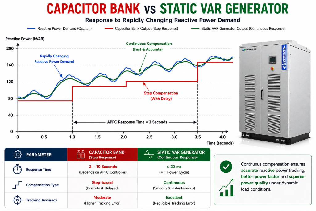
One of the most critical limitations of a conventional capacitor bank is its response time. Reactive power compensation is achieved by switching capacitor stages ON or OFF after the APFC controller detects a change in system power factor. Although this operating principle is effective for slowly varying loads, it cannot respond quickly enough to the rapidly changing reactive power demand of modern industrial electrical systems.
A conventional APFC panel performs reactive power compensation through a sequence of operations. First, the controller continuously measures system voltage and current using Current Transformers (CTs). To prevent unnecessary capacitor switching caused by transient load fluctuations, the controller typically waits for a predefined sampling interval before processing the measured power factor. Once compensation is required, it energizes the contactor coil, allowing the capacitor stage to connect to the electrical system. This complete detection, processing and switching sequence introduces an unavoidable response delay.
The total response time of a conventional APFC system can be approximated as:
Response Time = Detection Time + Controller Processing Time + Switching Time
Where:
- Detection Time = Time required to detect the power factor change.
- Controller Processing Time = Time taken by the APFC controller to determine the required capacitor stage.
- Switching Time = Mechanical or thyristor switching delay.
For a typical mechanically switched APFC panel:
- Detection Time ≈ 500 ms
- Controller Processing ≈ 100 ms
- Contactor Switching Delay ≈ 2.4 s
Therefore,
Response Time = 0.5 + 0.1 + 2.4 = 3 seconds
While a three-second response is acceptable for conventional motor-driven industries, it becomes inadequate for modern manufacturing environments where electrical loads change continuously.
Practical Example
Consider a manufacturing facility equipped with multiple Variable Frequency Drives (VFDs) controlling conveyor motors and production machinery.
Assume:
- Load changes every 50 ms
- Capacitor Bank response time = 3 s
The number of load variations occurring before the capacitor bank reacts is:
N = Response Time / Load Change Interval
Substituting the values:
N = 3 / 0.05
N = 60
Interpretation
Before the capacitor bank switches even once, the electrical load has already changed approximately 60 times.
During this period:
- Power factor continuously fluctuates.
- Reactive current increases.
- Voltage regulation deteriorates.
- Transformers and cables carry unnecessary current.
- Electrical losses increase.
- Overall power quality deteriorates.
This explains why conventional capacitor banks struggle to maintain accurate power factor correction in dynamic industrial applications.
Analysis of Compensation Error
Assume the instantaneous reactive power demand of an industrial load varies as:
QDemand = 100 + 40 sin (2πft) kVAR
Where:
- Average Reactive Power = 100 kVAR
- Maximum Variation = ±40 kVAR
A conventional capacitor bank can compensate only in fixed stages, for example:
- 75 kVAR
- 100 kVAR
- 125 kVAR
- 150 kVAR
Suppose the instantaneous reactive power demand becomes:
QDemand = 118 kVAR
The APFC controller selects the nearest available capacitor stage:
QCapacitor = 100 kVAR
Therefore,
QError = QDemand − QCapacitor
QError = 118 − 100
QError = 18 kVAR
A few milliseconds later, the demand increases further:
QDemand = 132 kVAR
Since the capacitor bank has not yet switched,
QCapacitor = 100 kVAR
Therefore,
QError = 132 − 100
QError = 32 kVAR
This compensation error continues until another capacitor stage is switched. As the load changes more rapidly, the mismatch between required and supplied reactive power becomes increasingly significant.
Impact on Line Current
Reactive power directly influences the current flowing through the electrical network.
The three-phase current associated with reactive power is:
I = Q / (√3 × V)
Assume:
- Uncompensated Reactive Power = 32 kVAR
- System Voltage = 415 V
Therefore,
I = 32000 / (1.732 × 415)
I ≈ 44.5 A
This means an additional 44.5 A flows through transformers, cables and switchgear solely because the capacitor bank could not respond quickly enough. This extra current increases I²R losses, transformer heating and voltage drop while reducing overall system efficiency.
Engineering Perspective
The limitation of conventional capacitor banks is not their reactive power capacity, but their inability to respond to rapidly changing load conditions. As industries increasingly adopt VFDs, servo drives, robotics and other dynamic loads, compensation speed becomes a critical design parameter.
Modern Static VAR Generators overcome this limitation by providing continuous, real-time reactive power compensation within approximately one power cycle. This significantly improves power factor correction, reduces unnecessary current flow, enhances voltage stability and delivers superior industrial power quality compared to conventional capacitor banks.
Industry Perspective
As industrial electrical systems continue to evolve, InPhase Power Technologies has developed advanced Static VAR Generator solutions that eliminate the response limitations of conventional capacitor banks. The ASTRA Standalone Static VAR Generator and Micro BHEEM Modular Static VAR Generator utilize intelligent DSP-based control and high-speed power electronic converters to provide accurate, continuous reactive power compensation for modern industrial applications.
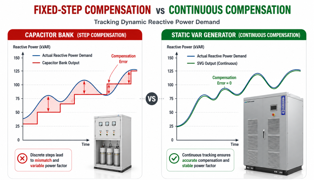
2. Fixed-Step Compensation Cannot Match Continuously Varying Reactive Power
A conventional capacitor bank compensates reactive power by switching fixed capacitor stages into or out of the electrical system. Each stage has a predefined reactive power rating, such as 25 kVAR, 50 kVAR or 100 kVAR. While this method provides satisfactory compensation for relatively stable electrical loads, it cannot accurately follow continuously varying reactive power demand.
Unlike conventional industrial loads, modern electrical systems rarely require reactive power in discrete values. Equipment such as Variable Frequency Drives (VFDs), servo drives, robotic systems and renewable energy inverters continuously change their operating conditions, causing reactive power demand to vary almost instantaneously. Since capacitor banks compensate only in fixed steps, a mismatch always exists between the required and supplied reactive power.
Engineering Principle
Reactive power supplied by a capacitor bank is given by:
Qc = V² / Xc
Where:
- Qc = Reactive power supplied by the capacitor (VAR)
- V = System voltage (V)
- Xc = Capacitive reactance (Ω)
Because Xc remains constant for a particular capacitor stage, the reactive power output is also fixed at the rated system voltage.
Unlike a Static VAR Generator, a capacitor bank cannot produce intermediate values such as 112 kVAR or 138 kVAR. It can only switch between available capacitor stages.
Practical Example
Consider an APFC panel having the following capacitor stages:
| Stage | Rating |
|---|---|
| 1 | 25 kVAR |
| 2 | 50 kVAR |
| 3 | 100 kVAR |
Assume the instantaneous reactive power demand changes throughout production.
| Reactive Power Demand | Capacitor Bank Output | Compensation Error |
|---|---|---|
| 92 kVAR | 75 kVAR | 17 kVAR |
| 118 kVAR | 100 kVAR | 18 kVAR |
| 136 kVAR | 125 kVAR | 11 kVAR |
| 149 kVAR | 150 kVAR | -1 kVAR |
Although the APFC controller always selects the nearest available capacitor combination, an unavoidable compensation error remains because reactive power demand changes continuously while capacitor banks compensate only in discrete steps.
Impact on Power Factor
Assume:
- Active Power = 500 kW
- Required Reactive Power = 118 kVAR
- Capacitor Bank Output = 100 kVAR
Remaining reactive power:
Qremaining = 118 − 100 = 18 kVAR
Apparent power becomes:
S = √(P² + Q²)
Substituting the values:
S = √(500² + 18²)
S ≈ 500.32 kVA
Power factor:
PF = P / S
PF = 500 / 500.32
PF ≈ 0.999
Although this example shows only a small error, in practical installations with multiple fluctuating loads and repeated switching delays, the cumulative effect results in continuous power factor variation, unnecessary reactive current and reduced compensation efficiency.
How a Static VAR Generator Eliminates Step Compensation
A Static VAR Generator does not depend on fixed capacitor stages. Instead, it continuously measures the reactive current demanded by the load and generates exactly the required compensation through an IGBT-based voltage source converter.
For the same operating condition:
| Reactive Power Demand | Capacitor Bank | Static VAR Generator |
|---|---|---|
| 92 kVAR | 75 kVAR | 92 kVAR |
| 118 kVAR | 100 kVAR | 118 kVAR |
| 136 kVAR | 125 kVAR | 136 kVAR |
| 149 kVAR | 150 kVAR | 149 kVAR |
Unlike capacitor banks, SVG output is continuously variable rather than step-based, resulting in almost zero compensation error and highly accurate power factor correction.
Engineering Perspective
The limitation of capacitor banks is not their compensation capacity but their resolution. Every capacitor bank operates in discrete kVAR steps, whereas industrial reactive power demand varies continuously. As the number of nonlinear and dynamic loads increases, this step-based compensation becomes increasingly inefficient. Static VAR Generator technology eliminates this limitation by providing smooth, continuously variable dynamic reactive power compensation, ensuring superior voltage stability and improved industrial power quality.
Industry Perspective
To address the limitations of conventional step-switched capacitor banks, InPhase Power Technologies offers advanced ASTRA Standalone Static VAR Generator and Micro BHEEM Modular Static VAR Generator solutions. By delivering continuously variable reactive power instead of fixed-step compensation, these systems maintain precise power factor correction under rapidly changing industrial load conditions
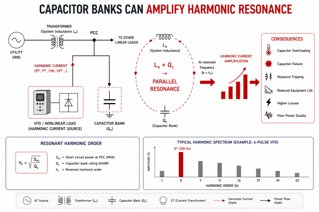
3. Capacitor Banks Can Amplify Harmonic Resonance
One of the most important engineering considerations when selecting a reactive power compensation system is its interaction with harmonic currents. A common misconception is that capacitor banks generate harmonics. In reality, capacitor banks are passive components and do not produce harmonic currents. However, when connected to an electrical system containing nonlinear loads, they can interact with the system inductance and create parallel resonance, significantly amplifying existing harmonics.
Modern industries widely use Variable Frequency Drives (VFDs), UPS systems, rectifiers, servo drives and EV chargers, all of which inject harmonic currents into the power network. If the resonant frequency of the electrical system coincides with one of these dominant harmonic frequencies, excessive harmonic current can flow through the capacitor bank, resulting in overheating, capacitor failure, nuisance tripping and reduced equipment life.
Understanding this phenomenon requires evaluating the resonant harmonic order of the electrical system.
Engineering Principle
For industrial power systems, the resonant harmonic order can be estimated using:
h = √(Ssc / Qc)
Where:
- h = Resonant harmonic order
- Ssc = Short-circuit capacity at the Point of Common Coupling (kVA)
- Qc = Capacitor bank rating (kVAR)
This equation provides a practical estimate of the harmonic order at which the capacitor bank and system inductance are likely to resonate.
Practical Example
Consider an industrial facility with the following electrical system:
- Short-circuit capacity at PCC = 25 MVA
- Installed capacitor bank = 1000 kVAR
Therefore,
h = √(25000 / 1000)
h = √25
h = 5
The calculated resonant harmonic order is therefore:
h = 5
For a 50 Hz power system,
Resonant Frequency = h × Fundamental Frequency
fr = 5 × 50
fr = 250 Hz ,
Now consider the harmonic spectrum produced by a typical 6-pulse Variable Frequency Drive.
| Harmonic Order | Frequency |
|---|---|
| 5th | 250 Hz |
| 7th | 350 Hz |
| 11th | 550 Hz |
| 13th | 650 Hz |
The calculated resonant frequency of 250 Hz exactly coincides with the dominant 5th harmonic generated by the VFD.
This is the condition under which harmonic resonance becomes highly probable.
Interpretation
When resonance occurs, the capacitor bank behaves like a low-impedance path at the resonant frequency, causing harmonic current to increase significantly.
Suppose the normal 5th harmonic current flowing through the capacitor is:
I₅ = 18 A
If resonance amplifies the harmonic current by only 2.5 times, the capacitor current becomes:
I₅(resonance) = 18 × 2.5
I₅(resonance) = 45 A
This additional harmonic current is superimposed on the fundamental current flowing through the capacitor.
The increased RMS current raises the operating temperature, accelerates dielectric ageing and reduces capacitor life. At the same time, transformers, cables and switchgear are subjected to additional harmonic loading, increasing system losses and reducing overall power quality.
In severe cases, protective devices may trip repeatedly even though the plant load has not increased.
Why Detuned Capacitor Banks Are Used
To reduce the possibility of resonance, many industrial capacitor banks incorporate detuned reactors connected in series with the capacitor stages.
The reactor shifts the resonant frequency below the dominant harmonic frequencies, reducing harmonic current amplification.
Although detuned capacitor banks significantly improve reliability, they still operate as fixed-step compensation systems and therefore cannot provide continuous dynamic reactive power compensation under rapidly changing load conditions.
How a Static VAR Generator Eliminates Resonance Risk
A Static VAR Generator (SVG) generates reactive power electronically using an IGBT-based Voltage Source Converter (VSC) instead of relying on large capacitor banks connected directly to the electrical network.
Because reactive current is synthesized electronically, an SVG does not create the same resonant LC circuit responsible for harmonic amplification. The converter continuously measures system current using Current Transformers (CTs), processes the information through a high-speed DSP controller and injects only the required reactive current in real time.
As a result:
- No parallel LC resonance is formed.
- Harmonic current amplification is minimized.
- Reactive power remains continuously controllable.
- Stable power factor correction is maintained even in harmonic-rich electrical systems.
This makes Static VAR Generators particularly suitable for industries using VFDs, UPS systems, robotics, renewable energy converters and other nonlinear loads.
Engineering Perspective
The engineering concern is not that capacitor banks generate harmonics, but that they can amplify existing harmonic currents when the system resonance coincides with dominant harmonic frequencies. A simple resonance calculation using the short-circuit capacity and capacitor bank rating can quickly indicate whether a conventional capacitor bank may operate near the 5th or 7th harmonic, where most industrial harmonic energy exists.
Modern Static VAR Generators overcome this limitation by generating reactive current electronically rather than through large capacitor banks, eliminating the primary mechanism responsible for harmonic resonance while delivering continuous reactive power compensation and improved industrial power quality.
Industry Perspective
For harmonic-rich industrial environments, InPhase Power Technologies offers ASTRA Standalone Static VAR Generator and Micro BHEEM Modular Static VAR Generator solutions that not only eliminate the risk of uncontrolled parallel resonance associated with conventional capacitor bank installations but also actively mitigate harmonic currents, improving power factor, reducing Total Harmonic Distortion (THD) and enhancing overall industrial power quality.
4. Reactive Power Output of Capacitor Banks Depends on System Voltage
One of the fundamental limitations of a conventional capacitor bank is that its reactive power output is directly proportional to the square of the system voltage. Unlike a Static VAR Generator (SVG), which electronically controls reactive current injection, a capacitor bank cannot maintain a constant reactive power output when the supply voltage fluctuates.
In modern industrial facilities, voltage variations occur due to motor starting, transformer loading, long cable feeders and rapidly changing production loads. During these conditions, the reactive power supplied by a capacitor bank changes automatically with the system voltage, even though the reactive power demand of the load may remain unchanged. As a result, the electrical system may experience under-compensation or over-compensation, leading to unstable power factor and reduced voltage regulation.
Engineering Principle
The reactive power supplied by a capacitor bank is given by:
Qc = V² / Xc
Where:
- Qc = Reactive Power (VAR)
- V = System Voltage (V)
- Xc = Capacitive Reactance (Ω)
Since the reactance of the capacitor remains constant,
Reactive Power ∝ Voltage²
This means even a small voltage variation produces a significantly larger change in reactive power output.
Practical Example
Consider a capacitor bank rated:
- Rated Voltage = 415 V
- Rated Reactive Power = 100 kVAR
Case 1 – Voltage Drops to 380 V
Using the voltage square relationship,
Qc = 100 × (380 / 415)²
Qc = 100 × 0.839
Qc ≈ 84 kVAR
Although the capacitor bank is rated for 100 kVAR, it now supplies only 84 kVAR.
The system therefore loses:
Reactive Power Loss = 100 − 84 = 16 kVAR
This reduction occurs automatically without any fault in the capacitor bank.
Case 2 – Voltage Rises to 440 V
Similarly,
Qc = 100 × (440 / 415)²
Qc = 100 × 1.124
Qc ≈ 112 kVAR
The same capacitor bank now supplies approximately 112 kVAR, resulting in 12% more reactive power than its rated value.
Interpretation
The table below illustrates the effect of voltage variation on capacitor output.
| System Voltage | Reactive Power Output |
|---|---|
| 380 V | 84 kVAR |
| 400 V | 93 kVAR |
| 415 V | 100 kVAR |
| 440 V | 112 kVAR |
Even though the capacitor bank itself has not changed, its reactive power output varies considerably with system voltage.
This behavior creates several engineering challenges:
- Reduced compensation during voltage sag.
- Excessive compensation during voltage rise.
- Fluctuating power factor.
- Poor voltage regulation.
- Reduced compensation accuracy.
These limitations become increasingly significant in industrial plants with continuously changing operating conditions.
How a Static VAR Generator Maintains Constant Compensation
A Static VAR Generator continuously measures both system voltage and load current using high-speed digital control algorithms. Instead of depending on capacitor reactance, it electronically controls the reactive current produced by its IGBT-based converter.
When system voltage decreases, the SVG automatically adjusts its converter output to maintain the required reactive power compensation within its operating limits. Likewise, during voltage rise, it reduces injected reactive current to prevent over-compensation.
Unlike a capacitor bank, the compensation provided by an SVG is controlled rather than voltage dependent, allowing accurate power factor correction over a wide operating voltage range.
Engineering Perspective
The performance of a conventional capacitor bank is inherently linked to system voltage because reactive power is proportional to the square of the applied voltage. Consequently, voltage fluctuations directly affect compensation performance, even when the reactive power requirement of the load remains unchanged.
A Static VAR Generator overcomes this limitation through closed-loop electronic current control, providing stable and predictable dynamic reactive power compensation independent of normal system voltage variations. This improves voltage stability, maintains accurate power factor and enhances the overall reliability of industrial electrical systems.
Industry Perspective
To deliver consistent reactive power compensation under varying grid conditions, InPhase Power Technologies offers ASTRA Standalone Static VAR Generator and Micro BHEEM Modular Static VAR Generator solutions. By using intelligent DSP-based control and high-speed IGBT converters, these systems maintain accurate compensation across changing voltage conditions, ensuring improved industrial power quality and reliable plant operation.
5. Conventional Capacitor Banks Cannot Correct Leading Power Factor
Power factor correction is traditionally associated with compensating lagging reactive power produced by inductive loads such as induction motors, transformers and reactors. Conventional capacitor banks are designed specifically for this purpose by supplying capacitive reactive power to offset the inductive demand.
However, modern industrial power systems no longer operate under purely inductive conditions. The widespread adoption of renewable energy systems, lightly loaded transformers, long underground cable networks, synchronous machines and power electronic converters can cause the electrical system to operate at a leading power factor.
Under these conditions, conventional capacitor banks become ineffective because they can only inject additional capacitive reactive power. Instead of improving the power factor, they may further increase the leading power factor, resulting in poor voltage regulation and utility power factor penalties.
Engineering Principle
Reactive power compensation can be classified as:
- Lagging Reactive Power (+Q) → Inductive loads
- Leading Reactive Power (−Q) → Capacitive loads
A conventional capacitor bank can only generate:
+Qc (Capacitive VARs)
It cannot absorb reactive power from the electrical network.
In contrast, a Static VAR Generator operates as a bidirectional reactive power source capable of both generating and absorbing reactive power.
Practical Example
Consider an industrial facility during normal production.
- Active Power = 600 kW
- Reactive Power = +300 kVAR
The apparent power is:
S = √(600² + 300²)
S ≈ 671 kVA
Therefore,
Power Factor = 600 / 671 = 0.894 Lagging
A capacitor bank improves the power factor by supplying capacitive reactive power.
Now consider the same facility during weekends or night shifts.
Large motors are switched OFF while long cable feeders and power electronic equipment remain energized.
Measured reactive power becomes:
Q = −120 kVAR
The power factor is now leading.
If a conventional capacitor bank remains connected, it injects additional capacitive reactive power.
Total reactive power becomes:
QTotal = −120 − 100
QTotal = −220 kVAR
Instead of improving the power factor, the capacitor bank drives the system further into the leading region.
Interpretation
Operating at a leading power factor can create several practical issues:
- Overvoltage under light-load conditions.
- Reduced voltage regulation.
- Utility power factor penalties.
- Increased switching operations of APFC panels.
- Unstable compensation during varying operating conditions.
Since capacitor banks cannot absorb reactive power, they are unable to correct this condition.
How a Static VAR Generator Solves the Problem
Unlike a conventional capacitor bank, a Static VAR Generator continuously measures system voltage and current and determines both the magnitude and direction of reactive power.
When the system requires capacitive compensation, the SVG injects reactive current.
When the system becomes leading, the SVG automatically absorbs reactive current from the network.
This bidirectional operation enables smooth transition between inductive and capacitive operating conditions without switching capacitor stages.
The operating principle can be summarized as:
| System Condition | Capacitor Bank | Static VAR Generator |
|---|---|---|
| Lagging Power Factor | Supplies VARs | Supplies VARs |
| Leading Power Factor | Cannot Absorb VARs | Absorbs VARs |
| Dynamic Load Variation | Step Compensation | Continuous Compensation |
Engineering Perspective
The limitation of a conventional capacitor bank is not its ability to improve lagging power factor, but its inability to respond when the electrical system becomes capacitive. Modern industrial facilities frequently experience changing operating modes throughout the day, making bidirectional reactive power control increasingly important.
By both generating and absorbing reactive power, Static VAR Generators provide stable power factor correction under inductive and capacitive operating conditions, improving voltage regulation and ensuring consistent industrial power quality.
Industry Perspective
To address both lagging and leading power factor conditions, InPhase Power Technologies offers ASTRA Standalone Static VAR Generator and Micro BHEEM Modular Static VAR Generator solutions. Their bidirectional reactive power capability enables accurate compensation across changing plant operating conditions, eliminating one of the key limitations of conventional capacitor banks.
6. Limited Scalability and Higher Lifecycle Maintenance
Although conventional capacitor banks provide an economical solution for reactive power compensation, expanding their compensation capacity is often neither simple nor economical. Industrial facilities rarely operate with fixed electrical loads throughout their lifetime. Production lines are upgraded, additional motors are installed, renewable energy systems are integrated and electrical demand continues to increase. As a result, the original capacitor bank sizing may no longer satisfy the plant’s reactive power requirements.
Unlike modular power electronic compensation systems, capacitor banks generally require additional capacitor stages, contactors, busbars, protection devices and panel modifications whenever the required compensation capacity increases. These modifications increase installation complexity, panel space requirements and maintenance effort.
Engineering Principle
The required reactive power compensation depends on the active load and target power factor.
The required capacitor rating is calculated as:
Qc = P (tan φ₁ − tan φ₂)
Where:
- Qc = Required Reactive Power Compensation (kVAR)
- P = Active Power (kW)
- φ₁ = Initial Power Factor Angle
- φ₂ = Desired Power Factor Angle
As the active load increases, the required capacitor bank capacity must also increase.
Practical Engineering Example
Consider an industrial plant with:
- Active Load = 800 kW
- Existing Capacitor Bank = 300 kVAR
- Existing Power Factor = 0.82
- Target Power Factor = 0.99
Initially,
Qc = 800 × (tan 34.92° − tan 8.11°)
Qc = 800 × (0.695 − 0.143)
Qc = 800 × 0.552
Qc ≈ 442 kVAR
Suppose the plant expands and the connected load increases to 1200 kW while maintaining the same operating conditions.
The new compensation requirement becomes:
Qc = 1200 × 0.552
Qc ≈ 662 kVAR
The original 300 kVAR capacitor bank is now significantly undersized.
The plant must install:
- Additional capacitor stages
- New contactors
- Higher-rated busbars
- Larger enclosure or additional APFC panel
- Updated protection devices
This often results in higher retrofit costs and longer shutdown periods.
Engineering Interpretation
Expanding a conventional capacitor bank is not simply a matter of adding more capacitors. Increasing compensation capacity often requires redesigning the entire APFC panel to accommodate higher fault levels, increased thermal loading and additional switching devices.
As plants continue to modernize, repeated panel modifications increase maintenance requirements and reduce installation flexibility.
How a Static VAR Generator Simplifies Expansion
Modern Static VAR Generators are available in modular architectures that allow compensation capacity to be increased by adding additional power modules instead of redesigning the complete compensation system.
For example:
| Required Compensation | Conventional Capacitor Bank | Modular SVG |
|---|---|---|
| 300 kVAR | New APFC Panel | Existing System |
| 450 kVAR | Additional Capacitor Stages | Add SVG Module |
| 600 kVAR | Larger Busbars & Protection | Add SVG Module |
| 800 kVAR | Complete Panel Upgrade | Add SVG Module |
This modular approach minimizes installation downtime and enables future expansion without major electrical redesign.
Engineering Perspective
Electrical systems rarely remain unchanged throughout their operating life. As industries expand production capacity and integrate new technologies, reactive power compensation systems must also adapt. Conventional capacitor banks often require significant hardware modifications to accommodate increased demand, whereas modular Static VAR Generators provide a scalable approach that supports future plant expansion with minimal disruption.
Industry Perspective
To support evolving industrial power systems, InPhase Power Technologies offers both ASTRA Standalone Static VAR Generator and Micro BHEEM Modular Static VAR Generator solutions. While ASTRA is suited for high-capacity standalone installations, Micro BHEEM enables modular expansion by adding power modules as reactive power demand increases, reducing retrofit complexity and supporting long-term system scalability.
5. Why Static VAR Generator Is Becoming the Preferred Choice
The growing adoption of Static VAR Generator (SVG) technology is not driven by a single advantage, but by its ability to address multiple engineering challenges that conventional capacitor banks cannot overcome simultaneously. As industrial electrical systems continue to evolve with Variable Frequency Drives (VFDs), renewable energy systems, robotic automation and other nonlinear loads, reactive power compensation must become faster, more accurate and more adaptive.
Unlike conventional capacitor banks, which compensate reactive power by switching fixed capacitor stages, a Static VAR Generator operates as a fully controlled power electronic system. It continuously monitors the electrical network, calculates the instantaneous reactive power requirement and injects or absorbs the exact reactive current required by the load. This closed-loop operating principle enables accurate dynamic reactive power compensation, regardless of changing load conditions.
The transition from passive compensation to intelligent electronic compensation fundamentally changes how industrial power factor correction is achieved. Rather than waiting for power factor to deviate before switching capacitor stages, an SVG continuously regulates its output current, maintaining stable system operation even during rapid load fluctuations.
How a Static VAR Generator Works
The operating principle of a Static VAR Generator can be summarized in four continuous steps:
Step 1 – System Measurement
Current Transformers (CTs) and voltage sensing circuits continuously measure the electrical parameters of the power system.
Step 2 – Real-Time Processing
A high-speed Digital Signal Processor (DSP) analyzes the measured signals and calculates the exact reactive current required to achieve the target power factor.
Step 3 – Compensating Current Generation
The DSP controls an IGBT-based Voltage Source Converter (VSC), which synthesizes the required compensating current using Pulse Width Modulation (PWM).
Step 4 – Reactive Current Injection
The generated reactive current is injected into the electrical network through the output filter, continuously compensating for inductive or capacitive reactive power as the load changes.
Unlike conventional capacitor banks, this entire process is performed continuously without mechanical switching, allowing the SVG to respond within approximately one power cycle.
Engineering Summary
The fundamental difference between the two technologies lies in the method of reactive power compensation.
| Conventional Capacitor Bank | Static VAR Generator |
|---|---|
| Passive compensation | Active electronic compensation |
| Fixed capacitor stages | Continuously variable output |
| Step switching | Real-time current control |
| Voltage-dependent output | Closed-loop current regulation |
| Capacitive VAR generation only | Bidirectional reactive power control |
Instead of switching between predetermined capacitor ratings, an SVG continuously adjusts its output according to the instantaneous requirements of the electrical system. This enables accurate power factor correction, improved voltage stability and enhanced industrial power quality, even under highly dynamic operating conditions.
Engineering Perspective
The evolution from capacitor banks to Static VAR Generators represents a shift from passive electrical compensation to intelligent power electronic control. While capacitor banks remain suitable for stable electrical systems with predictable reactive power demand, modern industrial facilities increasingly require compensation systems capable of responding to rapid load variations, harmonic-rich environments and continuously changing operating conditions.
By combining high-speed digital control with advanced power electronic converters, SVG technology provides a level of accuracy, flexibility and reliability that conventional capacitor banks cannot achieve through fixed-step compensation alone.
Industry Perspective
To address the demands of modern industrial power systems, InPhase Power Technologies offers both ASTRA Standalone Static VAR Generator and Micro BHEEM Modular Static VAR Generator solutions. Designed for applications ranging from heavy industries to space-constrained installations, these systems deliver fast, continuous and bidirectional reactive power compensation, enabling improved power factor correction and superior industrial power quality under dynamic operating conditions.
6. Capacitor Bank vs Static VAR Generator: Engineering Comparison
After understanding the operating principles and limitations of both technologies, the next step is to compare their practical performance under real industrial operating conditions. Although capacitor banks remain an effective solution for stable inductive loads, modern electrical systems increasingly demand faster, more accurate and continuously adaptive reactive power compensation. The following comparison summarizes the key engineering differences between conventional capacitor banks and Static VAR Generators, helping engineers select the appropriate technology based on application requirements rather than cost alone.
| Parameter | Conventional Capacitor Bank | Static VAR Generator (SVG) |
|---|---|---|
| Compensation Method | Fixed-step capacitor switching | Continuous compensation |
| Response Time | 2–10 s (Mechanical APFC) / 20–40 ms (Thyristor APFC) | ≤20 ms (≈1 Power Cycle) |
| Compensation Accuracy | Limited by capacitor step size | Near-continuous compensation |
| Reactive Power Control | Capacitive VAR generation only | Generates and absorbs reactive power |
| Leading Power Factor | Cannot correct | Corrects automatically |
| Voltage Dependency | Reactive power varies with V² | Closed-loop current control |
| Dynamic Load Handling | Limited | Excellent |
| Harmonic Resonance | Possible with system inductance | No uncontrolled system resonance |
| Harmonic Amplification Risk | Possible | Significantly reduced |
| Switching Method | Contactor / Thyristor | IGBT-based Voltage Source Converter |
| Power Quality Improvement | Moderate | High |
| Expansion | Requires additional capacitor stages and panel modifications | Modular expansion by adding SVG modules |
| Maintenance | Periodic capacitor and contactor replacement | Lower routine maintenance |
| Typical Applications | Stable motor loads, small industries | Dynamic industrial loads, VFDs, robotics, renewable energy, data centers |
Engineering Perspective
The comparison demonstrates that the primary difference between the two technologies is not simply response speed, but the overall method of reactive power compensation. Conventional capacitor banks rely on passive components and discrete switching, making them suitable for relatively stable electrical systems. In contrast, a Static VAR Generator actively regulates reactive current using power electronics and digital control, enabling accurate compensation under rapidly changing load conditions.
This distinction becomes increasingly important in facilities with high concentrations of nonlinear loads, renewable energy integration and automated manufacturing processes, where compensation accuracy and system stability directly influence power quality, equipment reliability and operational efficiency.
Industry Perspective
For applications with stable and predictable reactive power demand, a well-designed capacitor bank may remain a practical solution. However, industries requiring fast response, bidirectional reactive power control and reliable operation under dynamic conditions increasingly adopt InPhase ASTRA Standalone Static VAR Generator and Micro BHEEM Modular Static VAR Generator solutions to achieve superior power factor correction and long-term power quality performance.
7. Conclusion
The evolution of industrial electrical systems has fundamentally changed the requirements for reactive power compensation. Conventional capacitor banks continue to provide a reliable and cost-effective solution for applications with relatively stable inductive loads. However, as industries increasingly adopt Variable Frequency Drives (VFDs), robotic automation, renewable energy systems and other nonlinear loads, the limitations of fixed-step capacitor bank compensation become more apparent.
Throughout this article, we examined the major engineering challenges associated with conventional capacitor banks, including slow response to dynamic load changes, fixed-step compensation, harmonic resonance, voltage-dependent reactive power output, inability to correct leading power factor and limited scalability. While these limitations may not significantly affect simple electrical installations, they can reduce compensation accuracy, power factor stability and overall industrial power quality in modern facilities.
A Static VAR Generator (SVG) addresses these challenges through intelligent closed-loop control and high-speed power electronic conversion. By continuously measuring system conditions and generating or absorbing reactive current in real time, an SVG provides accurate dynamic reactive power compensation, bidirectional power factor correction and stable operation under rapidly changing load conditions. This makes SVG technology particularly suitable for manufacturing plants, process industries, renewable energy systems, data centers and other applications where electrical loads vary continuously.
Selecting the appropriate compensation technology should always be based on the operating characteristics of the electrical system rather than equipment cost alone. Conventional capacitor banks remain a practical choice for installations with predictable reactive power demand, whereas Static VAR Generators provide clear technical advantages in dynamic, harmonic-rich and mission-critical environments where compensation accuracy and system reliability are essential.
At InPhase Power Technologies, solutions such as the ASTRA Standalone Static VAR Generator and Micro BHEEM Modular Static VAR Generator are designed to meet these evolving industrial requirements by delivering fast, precise and intelligent reactive power compensation. By combining advanced power electronics with proven control technology, these solutions help industries improve power factor correction, enhance power quality, reduce electrical losses and support reliable long-term operation.
Whether designing a new electrical distribution system or upgrading an existing installation, understanding the engineering differences between conventional capacitor banks and Static VAR Generators is essential for selecting the most effective reactive power compensation solution.