
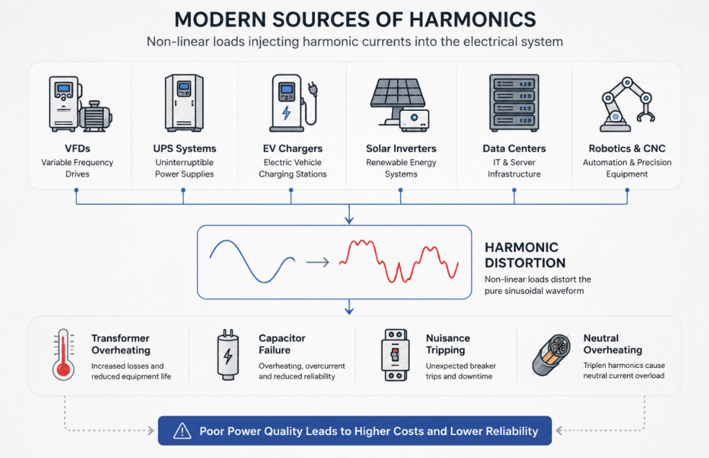
Today’s industrial facilities rely heavily on power electronics to drive process automation, optimize electromechanical control, and achieve aggressive energy efficiency targets. As a result, Active Filter Technology has become increasingly important for maintaining power quality in modern industrial electrical systems. While devices such as Variable Frequency Drives (VFDs), Switch Mode Power Supplies (SMPS), and high-efficiency LED lighting systems are fundamental to modern manufacturing, they also introduce severe power quality challenges into the electrical distribution grid.
Because these non-linear devices utilize semiconductor switching elements, they draw current in abrupt pulses rather than a continuous sine wave. This non-linear current profile injects harmonic frequencies back into the local distribution network, distorting the fundamental wave and precipitating a cascade of electrical and thermal inefficiencies.
For plant engineers and facility managers, mitigating these waveform distortions is a critical operational requirement. This article explores the 10 core advantages of implementing Active Filter Technology to solve modern industrial power quality challenges.
1. Immediate Compliance with IEEE 519-2022 Standards
Power quality enforcement is guided by rigorous international standards, which establish the maximum allowable electrical distortion at the Point of Common Coupling (PCC). Active Filter Technology is engineered to specifically target and resolve these compliance requirements.
The IEEE 519-2022 standard defines explicit limits for current distortion based on the relative strength of the power grid, expressed as the short-circuit ratio (Isc/IL).
| Short-Circuit Ratio (ISC/IL) | TDD Limit (%) | 3 ≤ h < 11 | 11 ≤ h < 17 | 17 ≤ h < 23 | 23 ≤ h < 35 | 35 ≤ h ≤ 50 |
|---|---|---|---|---|---|---|
| < 20 (Weak Grid) | 5.0 | 4.0 | 2.0 | 1.5 | 0.6 | 0.3 |
| 20 ≤ ISC/IL < 50 | 8.0 | 7.0 | 3.5 | 2.5 | 1.0 | 0.5 |
| 50 ≤ ISC/IL < 100 | 12.0 | 10.0 | 4.5 | 4.0 | 1.5 | 0.7 |
| 100 ≤ ISC/IL < 1000 | 15.0 | 12.0 | 5.5 | 5.0 | 2.0 | 1.0 |
| ≥ 1000 (Strong Grid) | 20.0 | 15.0 | 7.0 | 6.0 | 2.5 | 1.4 |
For voltage distortion, systems operating at 1.0 kV or below are strictly capped at an 8.0% Total Harmonic Distortion (THDv), with individual harmonic voltages strictly limited to 5.0%. By dynamically monitoring the PCC, modern Active Filter Technology guarantees these thresholds are continuously met, preventing utility curtailment and preserving grid stability, regardless of how the plant’s internal load profile fluctuates throughout the day.
2. Dynamic Mitigation of High Total Harmonic Distortion
The severity of harmonic pollution is quantified by Total Harmonic Distortion (THD). For current distortion (THDi), the mathematical definition evaluates the root-mean-square (RMS) amplitude of higher-order frequencies against the fundamental current (I1):
To provide a highly accurate representation of the harmonic impact relative to overall system capacity, Active Filter Technology sizing often relies on Total Demand Distortion (TDD), which evaluates distortion against the maximum demand load current (IL):
3. Immunity to Grid Resonance and Overloading
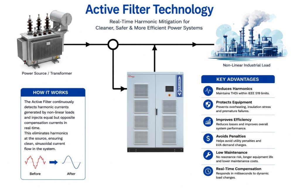
Historically, harmonic mitigation in industrial plants was achieved via passive harmonic filters (inductor-capacitor or LC circuits). While effective in stable conditions, passive filters alter the system impedance curve, creating new parallel resonance points. If background grid harmonics align with these frequencies, severe voltage amplification occurs.
Active Filter Technology entirely eliminates resonance risks. Because it functions as an active current source rather than a passive sink, it cannot be overloaded from the grid side. Once the internal DSP calculates that it has reached its maximum rated capacity, it intelligently caps its output and continues filtering safely without sustaining thermal damage.
4. Superior 3-Level NPC Inverter Topology
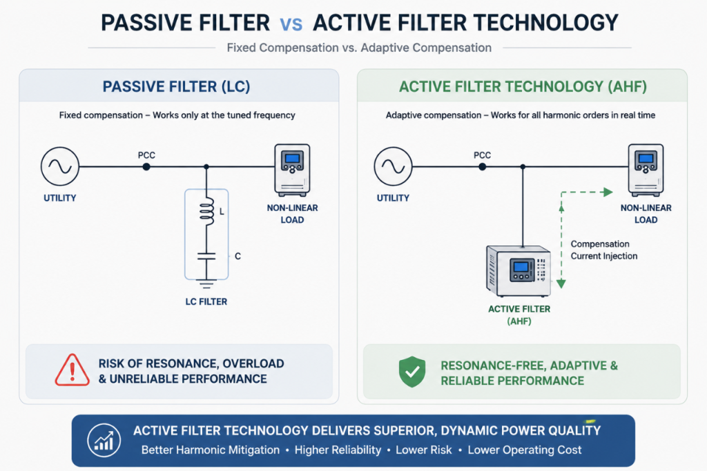
The core operational engine of advanced Active Filter Technology is its power electronic inverter. Leading systems have transitioned from traditional 2-level topologies to highly advanced 3-Level Neutral Point Clamped (NPC) architectures.
In a 3-level NPC topology, the DC bus is split by a series capacitor bank, providing a third voltage level. This architecture yields profound technical advantages:
Reduced Switching Losses: Because each IGBT only switches half of the total DC bus voltage, switching losses are drastically reduced, allowing operation at efficiency levels exceeding 98%.
Superior Waveform Quality and LCL Reduction: The middle voltage step produces a raw inverter output that closely resembles a true sine wave. This directly reduces the required size and inherent power loss of the external LCL interfacing filter.
- Lower Common-Mode Voltage (CMV): 3-level configurations naturally synthesize vectors that significantly reduce common-mode voltage, protecting downstream IT equipment and sensitive communication lines from stray high-frequency leakage currents.
5. Broad Spectrum and Simultaneous Mitigation
Multi-pulse VFDs dominate modern industrial floors. A standard 6-pulse drive follows the characteristic harmonic equation:
This means it primarily generates 5th, 7th, 11th, and 13th harmonics. In commercial environments and data centers, single-phase SMPS loads generate significant 3rd, 9th, and 15th zero-sequence “triplen” harmonics, which dangerously accumulate in neutral conductors.
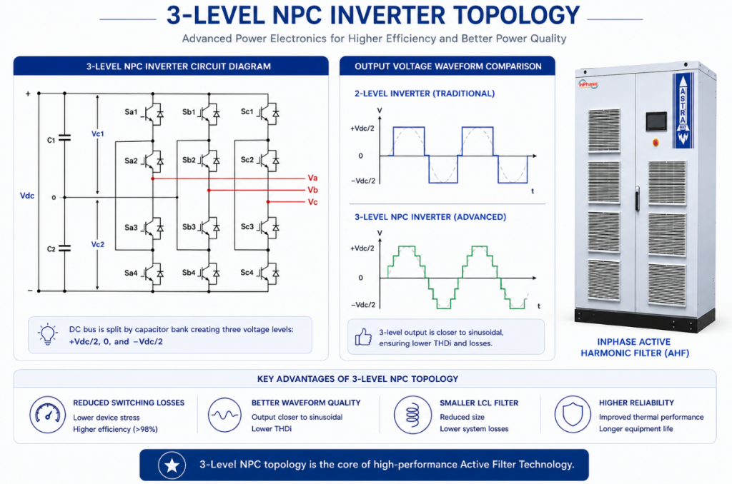
Active Filter Technology provides broad-spectrum coverage, dynamically tracking and canceling harmonics from the 2nd up to the 50th or 61st order simultaneously. Furthermore, in 4-wire configurations, they actively inject zero-sequence currents to eliminate neutral wire overloading, protecting mission-critical IT infrastructure from thermal fires.
6. Millisecond Response Time for Dynamic Loads
Passive LC filters provide fixed, static compensation, meaning they completely lack the ability to adapt to rapidly shifting industrial load profiles. As robotic welding systems, variable speed drives, automated cranes, and heavy lifts alter their load profiles instantaneously, a passive filter will severely over-compensate reactive power during sudden light load periods. This injects highly dangerous leading reactive power into the grid, causing massive overvoltage events and severe utility penalties.
The significantly lower individual switching losses inherent in 3-level NPC active filters allow them to operate safely at much higher apparent switching frequencies (often between 15 kHz to 20 kHz) without overheating. This dramatically improves the system’s dynamic tracking capability (di/dt) and reduces its full closed-loop reaction time. High-performance Active Filter Technology can identify load shifts and inject the exact necessary compensation current in under 20 milliseconds, providing a perfectly stable power profile even under the most chaotic, highly variable manufacturing conditions.
7. Precise Engineering Sizing for Guaranteed Results
Unlike passive mitigation solutions, which require complex, highly specialized grid impedance studies to evaluate resonance risks, Active Filter Technology allows for highly precise, mathematically predictable sizing using standard electrical parameters gathered from power quality analyzers.
Worked Example 1: Defining THDi An industrial chiller plant records a fundamental load current of 300 A and an aggregate RMS harmonic current of 90 A.
THDi = (90 / 300) × 100
Therefore:
THDi = 30%
The electrical system exhibits a THDi of 30%, which exceeds typical IEEE 519 recommendations and requires harmonic mitigation.
Worked Example 2: Sizing an Active Filter Targeting a strict 5.0% THDi compliance limit on a 415 V system with an initial RMS load current of 650 A and 38% THDi.
First, calculate the fundamental current:
I1 = 650 / √(1 + 0.38²)
Resulting in a fundamental current of 607.61 A.
Next, extract the initial and target harmonic currents:
Initial Harmonic Current: 230.89 A
Target Harmonic Current: 30.38 A
Calculate the required compensation current (assuming orthogonal dynamic targeting):
Icomp = √(230.89² − 30.38²) Resulting in a raw compensation current of 228.88 A. Applying a standard 1.20 engineering safety factor:
IAHF = 228.88 × 1.20
IAHF = 274.66 A
Therefore:
A standard 300 A Active Harmonic Filter should be selected to guarantee compliance.
8. True Power Factor Optimization and Penalty Avoidance
Harmonics fundamentally alter the entire dynamics of power factor correction. In a purely linear system, the power factor is solely determined by the phase angle difference between voltage and current, known as the Displacement Power Factor (cos θ). However, the geometric relationship of apparent power dictates that harmonic distortion introduces a critical third dimension to the traditional power triangle:
kVA² = kW² + kVAR² + kVAharmonic²
Consequently, the True Power Factor is calculated as:
True PF = Displacement PF × Distortion PF
Where the Distortion Power Factor is derived directly from the THDi:
Distortion PF = 1 / √(1 + THDi²)
Worked Example 3: ROI via Penalty Avoidance A facility draws 371.24 kW with a Displacement PF of 0.85 and a THDi of 38%.
Calculate Distortion Power Factor
DPF = 1 / √(1 + 0.38²)
DPF = 0.9348
Calculate True Power Factor
True PF = 0.85 × 0.9348
True PF = 0.7946
The facility therefore draws:
Apparent Power = 467.22 kVA
The new True PF is optimized to 0.9787. Apparent power drops to 379.31 kVA. By entirely bypassing kVAh billing penalties, facilities rapidly recover their capital investment.
9. Comprehensive Upgrade Over Passive Mitigation
When critically evaluating modern power quality solutions, Active Filter Technology represents a significant generational leap over legacy fixed-trap systems across every conceivable engineering parameter. Passive filters require massive, bulky footprints due to large capacitor arrays and heavy iron-core reactors, and they suffer from significant lifecycle degradation. Over time, passive capacitors naturally lose capacitance due to dielectric aging, which fundamentally alters the resonant tuning frequency of the trap, rendering it ineffective or dangerously resonant with the grid. Conversely, Active Filter Technology utilizes reliable, solid-state digital electronics, requiring vastly less space and delivering consistent, untampered performance over decades of operation.
| Technical Specification | Passive Harmonic Filter | Active Harmonic Filter |
|---|---|---|
| Mitigation Method | LC tuned circuit | DSP-controlled current injection |
| Harmonic Coverage | Single frequency | 2nd to 50th/61st order |
| Response Time | Fixed | < 20 ms |
| Resonance Risk | High | None |
| Overloading Risk | Possible | Current limited |
| Reactive Power | Fixed | Dynamic |
| Maintenance | High | Low |
| Monitoring | Limited | Real-time |
| Adaptability | Poor | Excellent |
10. Rapid Return on Investment and Extended Asset Lifecycle
Active Filter Technology delivers highly predictable financial returns across critical sectors:
Manufacturing: In environments dense with VFDs, harmonic currents cause severe eddy current losses (PEC ∝ h²) inside transformers. Active filters eliminate these high-frequency currents, reducing upstreamI²R copper losses by up to 35% and stabilizing transformer operating temperatures.
Renewable Energy & EV Charging: Solar farms, Battery Energy Storage Systems (BESS), and high-speed EV chargers require strict grid code compliance. Active filters operate alongside Static Var Generators (SVGs) to correct power factor, prevent grid resonance, and eliminate harmonic voltage flicker.
Asset Lifecycle: By removing constant thermal stress and voltage distortion, facilities observe a 25% to 40% increase in the physical lifespan of switchgear, cables, and motors, alongside massive reductions in unplanned maintenance and downtime.
Modern industrial power networks require intelligent, dynamic solutions. By actively neutralizing current distortion, dynamically optimizing True Power Factor, and generating measurable reductions in system losses, Active Filter Technology ensures absolute regulatory compliance while delivering a rapid, verifiable return on investment for the modern enterprise.