
Modern industrial facilities depend extensively on Active Harmonic Filters to address the growing power quality challenges introduced by advanced power electronic equipment. As industries adopt Variable Frequency Drives (VFDs), UPS systems, robotic automation, EV chargers, data centers, and renewable energy technologies, maintaining electrical system reliability has become increasingly difficult due to harmonic distortion. Selecting the right Active Harmonic Filter is therefore no longer just a procurement decision—it is a critical engineering decision that directly influences system reliability, operational efficiency, and compliance with international power quality standards.
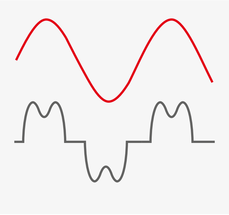
Unlike traditional linear loads, modern power electronic equipment employs high-speed semiconductor switching devices that draw non-sinusoidal current from the electrical supply. These current waveforms contain harmonic components that distort the fundamental waveform and propagate throughout the electrical distribution network. Excessive harmonic distortion can result in transformer overheating, capacitor bank failures, nuisance breaker tripping, increased cable losses, neutral conductor heating, premature equipment aging, and reduced overall system efficiency. As industrial facilities become more automated, these problems continue to increase in both frequency and severity.
International standards such as IEEE 519-2022 and the IEC 61000 series establish recommended limits for harmonic distortion at the Point of Common Coupling (PCC), making harmonic compliance an essential consideration during system design and equipment selection. Simply installing an Active Harmonic Filter does not guarantee compliance. Achieving effective harmonic mitigation depends on several engineering factors, including accurate harmonic measurements, proper filter sizing, installation location, response time, system architecture, and future load expansion.
This article presents ten essential engineering considerations that should be evaluated before selecting an Active Harmonic Filter for an industrial power system. It combines practical field experience, international standards, engineering calculations, and modern power quality practices to help consultants, plant engineers, system integrators, and facility managers make informed technical decisions and maximize the long-term performance of their harmonic mitigation investment.
IEEE 519 and IEC 61000: The Foundation of Harmonic Compliance
Before selecting an Active Harmonic Filter, it is essential to understand the international standards that govern harmonic distortion and power quality. Compliance with these standards not only ensures reliable operation of industrial electrical systems but also minimizes the risk of equipment failures, utility penalties, and future system upgrades.
Two of the most widely recognized standards in this field are IEEE 519-2022 and the IEC 61000 series. Together, these standards provide engineering guidelines for controlling harmonic distortion, maintaining acceptable voltage quality, and ensuring electromagnetic compatibility within industrial power systems.
IEEE 519-2022
IEEE 519-2022, Recommended Practice and Requirements for Harmonic Control in Electric Power Systems, is the most widely referenced standard for harmonic mitigation. Rather than specifying the design of harmonic filters, it establishes recommended limits for harmonic current and voltage distortion at the Point of Common Coupling (PCC)—the location where the customer’s electrical system connects to the utility supply.
The standard defines acceptable limits for:
- Total Harmonic Current Distortion (THDi)
- Total Demand Distortion (TDD)
- Total Harmonic Voltage Distortion (THDv)
- Individual harmonic components
These limits are based on the electrical strength of the utility network, represented by the ISC/IL ratio, where:
- ISC = Maximum available short-circuit current at the PCC
- IL = Maximum demand load current
A stronger electrical network can tolerate higher harmonic current levels, whereas weaker grids require stricter harmonic control. For this reason, an accurate harmonic study is essential before selecting the rating of an Active Harmonic Filter.
Table 1 summarizes the maximum harmonic current distortion limits specified by IEEE 519-2022 for different grid strengths.
| ISC / IL Ratio | TDD Limit (%) | 3 ≤ h < 11 | 11 ≤ h < 17 | 17 ≤ h < 23 | 23 ≤ h < 35 | 35 ≤ h ≤ 50 |
|---|---|---|---|---|---|---|
| < 20 (Weak Grid) | 5.0 | 4.0 | 2.0 | 1.5 | 0.6 | 0.3 |
| 20 – 50 | 8.0 | 7.0 | 3.5 | 2.5 | 1.0 | 0.5 |
| 50 – 100 | 12.0 | 10.0 | 4.5 | 4.0 | 1.5 | 0.7 |
| 100 – 1000 | 15.0 | 12.0 | 5.5 | 5.0 | 2.0 | 1.0 |
| > 1000 (Strong Grid) | 20.0 | 15.0 | 7.0 | 6.0 | 2.5 | 1.4 |
IEC 61000 Series
While IEEE 519 focuses primarily on harmonic limits at the PCC, the IEC 61000 family of standards addresses electromagnetic compatibility (EMC) and power quality requirements for electrical equipment and industrial installations.
Depending on the application, different parts of the IEC 61000 series provide guidance on:
- Harmonic current emission limits
- Voltage distortion limits
- Electromagnetic compatibility
- Industrial power quality requirements
- Network planning and harmonic assessment
These standards help manufacturers, consultants, and plant engineers design electrical systems that operate reliably without causing unacceptable interference to other connected equipment.
Why These Standards Matter
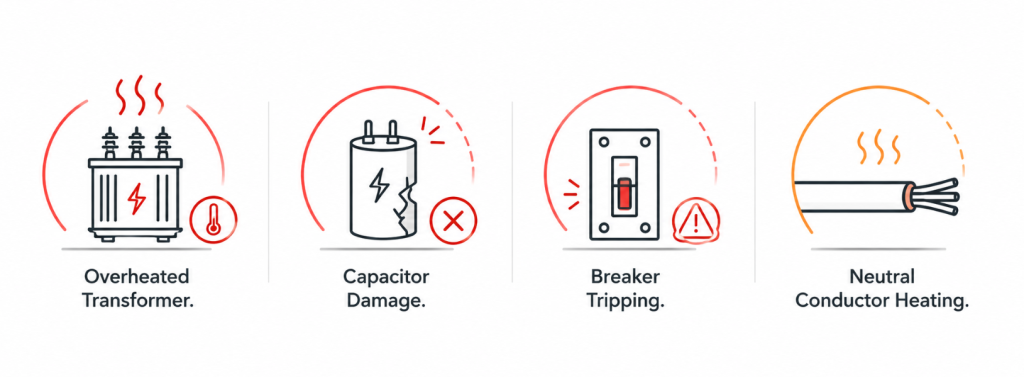
Meeting harmonic standards is about more than regulatory compliance. Excessive harmonic distortion can lead to:
- Transformer overheating
- Capacitor bank failures
- Nuisance circuit breaker tripping
- Increased I²R losses
- Neutral conductor overheating
- Reduced equipment lifespan
- Lower system efficiency
Selecting an Active Harmonic Filter based solely on load current or catalogue ratings does not guarantee compliance. Proper harmonic measurements, accurate filter sizing, installation location, and system characteristics must all be considered to achieve the performance required by IEEE 519 and IEC 61000.
For this reason, compliance with international standards should be viewed as the starting point of every harmonic mitigation project rather than the final objective.
1. Understand the Problem Before Selecting the Solution
Many facilities begin looking for an Active Harmonic Filter after experiencing recurring electrical problems. Transformers may operate at unusually high temperatures, capacitor banks may fail repeatedly, or protective devices may trip unexpectedly during production. In some cases, sensitive equipment experiences malfunction, while in others the utility may raise concerns regarding power quality.
Before selecting an AHF, it is important to clearly define the problem that needs to be solved. Harmonic mitigation should never be treated as a generic solution. A system designed to eliminate neutral current problems in a commercial building may differ significantly from a system intended to reduce distortion in a large manufacturing facility.
Understanding the actual operating issues allows the engineering team to establish realistic objectives and select the most appropriate mitigation strategy.
Example:
A packaging facility experienced repeated capacitor bank failures every six months. A harmonic study later revealed that newly installed VFDs had increased the fifth harmonic levels, causing capacitor overheating and premature failure.
2. Conduct a Harmonic Study Before Purchasing
One of the most common mistakes in harmonic mitigation projects is selecting equipment without first understanding the electrical behavior of the facility. A proper harmonic study provides the information necessary to determine the severity of the problem and the level of compensation required.
Parameters such as Total Harmonic Current Distortion (THDi), Total Harmonic Voltage Distortion (THDv), harmonic spectrum, and load profiles should be measured under actual operating conditions. The study should ideally capture production cycles, peak loading periods, and varying operating conditions.
Without these measurements, the selected filter may be oversized, resulting in unnecessary capital expenditure, or undersized, preventing the facility from achieving the desired performance. A harmonic study is therefore not an optional step but a fundamental requirement for proper system design.
Example:
Two similar manufacturing plants selected different filter capacities. The facility that performed a harmonic study installed a significantly smaller AHF while achieving the same performance, reducing project costs considerably.
3. Identify the Sources of Harmonics
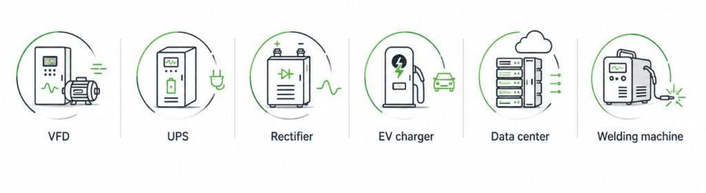
Not all electrical loads contribute equally to harmonic distortion. Modern industrial facilities contain numerous nonlinear loads that draw current in a non-sinusoidal manner. Variable frequency drives, UPS systems, welding equipment, rectifiers, battery chargers, data centers, and EV charging infrastructure are among the most common harmonic sources.
The type, size, and operating characteristics of these loads significantly influence the harmonic profile of the facility. A plant dominated by six-pulse drives may exhibit strong fifth and seventh harmonics, while facilities containing large numbers of electronic power supplies may experience substantial triplen harmonics.
Identifying these sources helps engineers determine where harmonics originate and how the AHF should be applied.
Example:
A water treatment facility introduced several VFD-driven pumps to improve energy efficiency. Although motor control improved, harmonic distortion increased, resulting in transformer heating and increased voltage distortion.
4. Proper Sizing Is Critical
The effectiveness of an Active Harmonic Filter depends heavily on proper sizing. A common misconception is that the filter rating should simply match the load current. In reality, the filter compensates harmonic current rather than the total load current.
The required filter capacity depends on measured harmonic current, operating conditions, load diversity, and future expansion plans. An undersized filter may operate continuously at maximum capacity without achieving the required distortion levels. Conversely, excessive oversizing increases investment costs without providing additional benefits.
Proper sizing should always consider both current operating conditions and anticipated future requirements.
Worked Example: Estimating Required AHF Capacity
Consider a facility with:
- Load current = 500 A
- Measured THDi = 35%
The harmonic current can be estimated as:
IH = I × THDi IH = 500 × 35% IH = 175 A
In this case, the AHF should be selected based on the harmonic current rather than the total load current.
Allowing an additional 20% margin for future expansion:
Required AHF Capacity:
175 × 1.2 = 210 A
Therefore, a 200–250 A AHF would be a more appropriate selection than a 500 A filter.
This simple calculation demonstrates why harmonic studies are essential before equipment selection.
5. Evaluate Dynamic Load Conditions
Electrical loads in industrial facilities rarely operate at constant demand. Production lines start and stop, motors accelerate and decelerate, welding machines switch rapidly, and robotic systems continuously change their operating cycles. These dynamic load variations cause harmonic current and reactive power demand to fluctuate within milliseconds, creating a continuously changing power quality environment.
Unlike conventional passive filters, an Active Harmonic Filter continuously measures the load current, identifies the harmonic spectrum, and injects an equal but opposite compensation current in real time. The effectiveness of this process depends heavily on the filter’s response time. A slow control system cannot compensate for rapidly changing harmonic currents, allowing distortion to propagate through the electrical distribution network before corrective action is taken.
Applications such as robotic welding cells, stamping presses, crane systems, high-speed packaging machines, and Variable Frequency Drives (VFDs) frequently experience rapid load transitions. In these environments, harmonic levels measured during one production cycle may differ significantly from those measured only a few milliseconds later. An Active Harmonic Filter designed for dynamic industrial applications must therefore maintain stable compensation under continuously changing operating conditions rather than only under steady-state operation.
Modern AHFs achieve this performance through high-speed digital signal processors (DSPs), fast current sensors, and closed-loop control algorithms capable of updating the compensation current in real time. Depending on the product architecture, response times are typically less than 20 milliseconds, enabling continuous harmonic mitigation without interrupting normal plant operation.
When comparing Active Harmonic Filters, response time should not be evaluated as an isolated specification. It should be considered together with harmonic detection accuracy, controller performance, current tracking capability, and compensation stability under rapidly varying loads.
Engineering Insight
A filter with a fast response time but poor current tracking accuracy may still leave significant residual harmonic distortion. Likewise, a highly accurate filter with a slow controller may fail to compensate rapidly changing loads. Effective harmonic mitigation depends on the combined performance of the sensing system, control algorithm, power converter, and output filter.
Example
An automotive manufacturing plant equipped with robotic welding stations experienced large fluctuations in harmonic current during each production cycle. Harmonic levels changed continuously as multiple welding robots started and stopped independently. A conventional fixed compensation solution could not respond to these rapid variations. By installing an Active Harmonic Filter with high-speed DSP control and millisecond response capability, the facility maintained stable harmonic compensation throughout the production process, reducing nuisance breaker tripping and improving overall power quality.
6. Consider Future Expansion
Electrical distribution systems rarely remain unchanged throughout their service life. Production capacity increases, additional process lines are commissioned, and new power electronic loads are integrated as operational requirements evolve. Expansion projects that initially appear minor can significantly alter the harmonic profile of an electrical network, affecting both harmonic distortion levels and reactive power demand.
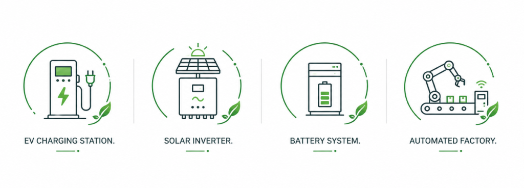
Industrial facilities are also adopting technologies such as EV charging infrastructure, solar photovoltaic systems, Battery Energy Storage Systems (BESS), high-efficiency Variable Frequency Drives (VFDs), and automated production equipment. While these technologies improve productivity and energy efficiency, they also increase the number of non-linear loads connected to the system, often resulting in higher harmonic currents than originally anticipated.
Selecting an Active Harmonic Filter based solely on present operating conditions can therefore limit future system performance. A filter that is correctly sized for today’s harmonic load may become inadequate after plant expansion, requiring additional equipment or complete replacement. Considering future electrical growth during the initial design stage helps avoid unnecessary capital expenditure and minimizes disruption during later upgrades.
Modular Active Harmonic Filters provide greater flexibility for facilities expecting future expansion. Additional power modules can be installed as harmonic levels increase, allowing the compensation capacity to grow alongside the electrical system without replacing the original installation. This approach reduces lifecycle costs while extending the useful life of the harmonic mitigation system.
Expansion planning should also consider the available switchboard space, cable routing, ventilation requirements, communication infrastructure, and spare feeder capacity. Addressing these factors during the initial project simplifies future upgrades and reduces commissioning time.
Engineering Insight
Electrical systems are typically designed for an operational life of 10 to 20 years, whereas manufacturing processes and connected loads may change several times during that period. Designing harmonic mitigation with future expansion in mind ensures that the electrical infrastructure remains compliant with IEEE 519-2022 even as new non-linear loads are introduced.
Example
A pharmaceutical manufacturing facility initially installed an Active Harmonic Filter to mitigate harmonics generated by its production lines. Three years later, an expansion project added additional VFD-driven process equipment and a new packaging line, increasing the facility’s harmonic current beyond the original design assumptions. Because a modular Active Harmonic Filter had been selected during the initial installation, additional filter modules were integrated into the existing system without replacing the original equipment, reducing project cost and minimizing production downtime.
7. Look Beyond Harmonic Mitigation
Harmonic distortion is rarely the only power quality issue affecting an industrial electrical system. Facilities experiencing excessive harmonics often encounter additional problems such as poor power factor, reactive power demand, phase current imbalance, and high neutral currents. Addressing only one of these issues may improve a specific measurement while leaving the overall electrical system operating below its optimum performance.
Modern Active Harmonic Filters have evolved beyond dedicated harmonic compensation devices. Many platforms are capable of performing multiple power quality functions simultaneously, allowing a single system to improve overall network performance rather than addressing individual problems with separate equipment.
Depending on the converter architecture and control strategy, an Active Harmonic Filter may provide:
- Harmonic current compensation
- Dynamic reactive power compensation
- Power factor improvement
- Three-phase load balancing
- Neutral current reduction
- Continuous power quality monitoring
This multifunctional approach simplifies system design and can eliminate the need for separate capacitor banks, phase balancing equipment, or neutral current mitigation devices in suitable applications. Fewer dedicated devices reduce switchboard complexity, simplify maintenance, and improve long-term system reliability.
Reactive power compensation is a good example. Harmonic mitigation alone does not correct displacement power factor. If a facility operates with significant inductive loads, additional reactive power compensation is required to maintain an acceptable cos φ and avoid utility penalties. Many modern Active Harmonic Filters can compensate harmonic currents and reactive power simultaneously, improving both THDi and overall power factor under changing load conditions.
Similarly, facilities with large numbers of single-phase electronic loads often experience excessive neutral current caused by triplen harmonics. By compensating these harmonic components at their source, an Active Harmonic Filter reduces neutral conductor loading and minimizes overheating of cables and distribution equipment.
The objective should therefore extend beyond achieving a lower THDi value. The real measure of success is an electrical system that operates with lower losses, improved voltage stability, higher equipment reliability, and reduced maintenance requirements.
Engineering Insight
Power quality problems are interconnected. Harmonic distortion increases RMS current, which raises I²R losses, transformer temperature, and voltage distortion. Correcting only one parameter rarely delivers the maximum operational benefit. A comprehensive power quality solution should address harmonic distortion, reactive power, load balance, and system stability as a complete engineering problem rather than as separate issues.
Practical Example
A food processing plant initially planned to install an Active Harmonic Filter solely to reduce harmonic distortion produced by its VFD-driven production lines. During the power quality assessment, engineers also identified poor power factor caused by large induction motors and elevated neutral currents resulting from numerous single-phase electronic loads. A multifunctional Active Harmonic Filter capable of simultaneous harmonic mitigation and reactive power compensation improved THDi, increased the plant power factor to the utility target, reduced neutral conductor heating, and eliminated the need for additional power factor correction equipment.
8. Understanding the Technology Behind Modern Active Harmonic Filters
Selecting an Active Harmonic Filter involves more than comparing current ratings or harmonic attenuation percentages. The long-term performance of the system is determined by the converter topology, control architecture, signal processing capability, and the speed at which the filter responds to changing load conditions. These design elements directly influence harmonic compensation accuracy, operating efficiency, scalability, and overall system reliability.
At its core, an Active Harmonic Filter operates as a controlled current source. High-speed current transformers continuously measure the load current, while a digital controller separates the fundamental component from the harmonic components. The controller then commands a power electronic converter to inject an equal and opposite compensation current, effectively cancelling the harmonics before they propagate through the electrical distribution system.
The entire compensation process is performed continuously using a closed-loop control system, allowing the filter to adapt automatically as operating conditions change. Unlike passive harmonic filters, whose performance depends on fixed inductance and capacitance values, an Active Harmonic Filter continuously adjusts its output according to the measured harmonic spectrum.
Three-Level IGBT Topology
The inverter is the heart of every Active Harmonic Filter. Modern systems increasingly employ a three-level IGBT topology rather than a conventional two-level converter. By introducing an additional voltage level, the inverter produces an output waveform that more closely approximates a sinusoidal wave, reducing switching stress and improving current quality.
For harmonic mitigation applications, this architecture provides several practical advantages:
- Lower switching losses
- Improved current waveform quality
- Reduced current ripple
- Lower electromagnetic interference (EMI)
- Higher conversion efficiency
- Reduced stress on semiconductor devices
The ASTRA platform employs a 3-Level IGBT topology together with closed-loop control, enabling high-efficiency harmonic compensation in industrial environments.
Closed-Loop Digital Control
Industrial harmonic levels rarely remain constant. Production lines start and stop, Variable Frequency Drives continuously change speed, and welding equipment produces rapidly varying current waveforms. Maintaining low harmonic distortion under these conditions requires continuous measurement and control rather than fixed compensation.
Modern Active Harmonic Filters use closed-loop digital control to monitor load current in real time. High-speed Digital Signal Processors (DSPs) analyse the measured waveform, determine the magnitude and phase angle of the harmonic components, and calculate the required compensation current. This process repeats continuously, allowing the filter to maintain stable performance under dynamic loading conditions.
The ASTRA platform is based on a multi-core DSP architecture with intelligent adaptive control, enabling continuous harmonic compensation without manual tuning.
Harmonic Compensation Capability
Industrial facilities rarely generate a single harmonic order. Variable Frequency Drives, UPS systems, rectifiers, welding equipment, and inverter-based loads produce multiple harmonic components simultaneously.
Rather than targeting only one or two frequencies, modern Active Harmonic Filters analyse the complete harmonic spectrum and compensate multiple harmonic orders in parallel.
Depending on the product configuration, the ASTRA Active Harmonic Filter supports:
- Harmonic compensation up to the 50th or 61st harmonic order
- Up to 20 selectable harmonic frequencies
- Harmonic attenuation of up to 99%
- Simultaneous harmonic mitigation and reactive power compensation
- Fundamental current balancing
- Neutral current compensation for applicable ratings
These capabilities allow a single platform to address a wide range of industrial power quality problems without requiring multiple dedicated devices.
Dynamic Response
A compensation algorithm is only effective if it can respond before harmonic levels change again. High-speed industrial processes such as robotic welding, rolling mills, automated production lines, and high-speed packaging systems generate rapidly varying harmonic currents that cannot be effectively controlled by slow compensation systems.
Modern Active Harmonic Filters therefore combine high-speed current sensing, DSP-based control, and fast-switching power electronics to maintain continuous compensation under changing load conditions.
According to the ASTRA product specifications, the system provides a reaction time of 0.1 ms, with a response time of approximately one power cycle, enabling stable harmonic compensation during rapidly changing industrial operating conditions.
Modular Architecture and Scalability
Electrical systems expand throughout their operational life. New production lines, Variable Frequency Drives, renewable energy systems, and EV charging infrastructure all contribute additional harmonic currents that may exceed the original design assumptions.
To accommodate future expansion, many modern Active Harmonic Filters adopt a modular architecture. Individual power modules can be added in parallel as harmonic demand increases, eliminating the need to replace the original installation.
The ASTRA Modular Active Harmonic Filter supports parallel operation of up to 32 units, allowing compensation capacity to increase alongside plant expansion while maintaining a compact installation footprint.
Monitoring and System Integration
Power quality management extends beyond harmonic compensation. Continuous monitoring provides valuable information on system performance, harmonic trends, operating conditions, and maintenance requirements.
Modern Active Harmonic Filters integrate with industrial automation systems through standard communication protocols, allowing engineers to monitor electrical parameters from SCADA and Energy Management Systems.
Typical monitoring functions include:
- Harmonic spectrum
- THDi and THDv
- Waveform display
- Vector diagrams
- Compensation current
- Event and fault logging
- Panel diagnostics
The ASTRA platform supports Modbus RS-485 communication, a 7-inch colour HMI, and cloud-based remote monitoring and diagnostics, enabling real-time supervision of system performance.
9. Installation Location Matters
The performance of an Active Harmonic Filter depends not only on its electrical rating but also on its installation location within the power distribution system. Even a correctly sized filter may fail to achieve the desired harmonic reduction if it is installed at an inappropriate point in the electrical network.
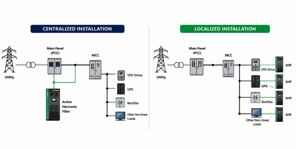
The installation strategy should be determined by the distribution architecture, the location of non-linear loads, and the objective of the harmonic mitigation project. In practice, Active Harmonic Filters are generally installed using either a centralized or a localized compensation approach.
Centralized Compensation
In a centralized configuration, the Active Harmonic Filter is installed at the Main Low Voltage (MLV) switchboard or at the Point of Common Coupling (PCC), where it monitors the combined load current of the entire facility.
This approach is suitable when harmonic-producing loads are distributed throughout the plant or when the primary objective is compliance with IEEE 519-2022 at the PCC. A single filter can compensate harmonics generated by multiple feeders, simplifying system design and reducing installation complexity.
Typical applications include:
- Manufacturing facilities
- Commercial buildings
- Data centers
- Hospitals
- Water treatment plants
The effectiveness of centralized compensation depends on the total harmonic current flowing through the main incomer and the diversity of connected loads.
Localized Compensation
In some facilities, a single piece of equipment generates a significant portion of the harmonic distortion. Typical examples include:
- Large Variable Frequency Drives
- Electric Arc Furnaces
- High-power UPS systems
- Rolling mills
- Welding systems
- Rectifier installations
In these cases, installing the Active Harmonic Filter close to the harmonic source prevents distortion from propagating through the rest of the electrical distribution system. This approach reduces harmonic current in upstream transformers, busbars, and cables while improving power quality for other connected equipment.
Localized compensation is particularly effective when a small number of large non-linear loads dominate the facility’s harmonic profile.
Factors Influencing Installation Location
Selecting the optimum installation point requires more than identifying where harmonics are present. The following engineering factors should also be evaluated during system design:
- Results of the harmonic study
- Distribution network configuration
- Harmonic current magnitude and spectrum
- Future plant expansion
- Available switchboard space
- Cable routing and CT installation
- Ventilation and cooling requirements
- Accessibility for maintenance
- Communication with SCADA or Energy Management Systems
Ignoring these factors may reduce compensation effectiveness, complicate maintenance activities, or increase future upgrade costs.
Engineering Recommendation
No single installation method is suitable for every facility. A centralized installation may provide the most economical solution for plants with multiple distributed harmonic sources, while localized compensation often delivers superior performance when one or two major non-linear loads dominate the harmonic profile.
For complex industrial facilities, the installation strategy should always be determined from a detailed harmonic study, electrical single-line diagram (SLD), and future expansion plan rather than from equipment ratings alone.
Practical Example
A steel processing plant experienced excessive harmonic distortion caused primarily by two high-capacity Variable Frequency Drives supplying the rolling mill. Instead of installing a single centralized Active Harmonic Filter at the main switchboard, engineers installed dedicated filters adjacent to each VFD panel. This localized approach reduced harmonic current before it propagated through the distribution network, lowering transformer loading and improving overall power quality throughout the facility.
10. Monitoring and Communication Features Are Increasingly Important
Power quality management does not end after commissioning. Continuous monitoring enables maintenance teams to verify harmonic performance, detect abnormal operating conditions, and evaluate long-term system behaviour without relying solely on periodic site measurements.
Modern Active Harmonic Filters incorporate built-in monitoring functions that provide real-time visibility of key electrical parameters, including THDi, THDv, load current, compensation current, power factor, alarms, and event logs. This information helps engineers identify developing issues before they affect plant operation.
Communication capability is equally important. Standard industrial protocols such as Modbus RTU and Modbus TCP/IP allow the Active Harmonic Filter to integrate with SCADA, Building Management Systems (BMS), and Energy Management Systems (EMS), providing centralized monitoring of power quality across the facility.
The ASTRA Active Harmonic Filter includes a 7-inch colour HMI, Modbus RS-485 communication, and cloud-based remote monitoring, enabling engineers to monitor system performance, review historical trends, and perform diagnostics without being physically present at the installation site.
Engineering Insight
When comparing Active Harmonic Filters, monitoring capabilities should be considered alongside harmonic compensation performance. Access to real-time operating data simplifies troubleshooting, supports predictive maintenance, and provides documented evidence of long-term compliance with power quality requirements.
Evaluate the Supplier, Not Just the Equipment
The long-term success of an AHF installation depends not only on the product but also on the capabilities of the supplier. Site studies, application engineering, commissioning support, and after-sales service play a critical role in achieving the desired results.
An experienced supplier can assist with harmonic studies, system design, equipment selection, and performance verification. Local technical support can significantly reduce troubleshooting time and improve system reliability.
When evaluating proposals, organizations should consider the supplier’s engineering expertise, service capabilities, and commitment to long-term support rather than focusing exclusively on equipment cost.
Will the Investment Deliver a Return?
An Active Harmonic Filter should be evaluated as a long-term investment in electrical system reliability rather than simply as a power quality device. While harmonic mitigation improves compliance with IEEE 519, its financial value is realized through lower operating costs, improved equipment reliability, and reduced production interruptions.
Excessive harmonic distortion increases RMS current, resulting in higher I²R losses, transformer heating, capacitor bank failures, nuisance breaker tripping, and premature aging of electrical equipment. These issues often lead to unplanned maintenance, reduced equipment life, and costly production downtime. By maintaining harmonic distortion within acceptable limits, an Active Harmonic Filter helps minimize these operational risks.
Financial benefits may include:
- Reduced equipment maintenance and replacement costs
- Lower transformer and cable losses
- Improved power factor when reactive power compensation is available
- Reduced utility penalties related to poor power quality
- Increased service life of transformers, capacitor banks, and motors
- Higher electrical system reliability and plant availability
The economic return depends on the operating profile of the facility, the severity of harmonic distortion, electricity tariff structure, and the value of uninterrupted production. Facilities with continuously operating non-linear loads typically achieve the fastest return on investment because the filter operates under high utilization throughout the year.
Engineering Insight
The value of an Active Harmonic Filter should not be assessed solely by energy savings. Avoiding a single transformer failure, capacitor bank replacement, or production shutdown can justify the investment far more effectively than reductions in electricity consumption alone. Evaluating the total lifecycle cost—including maintenance, downtime, and equipment replacement—provides a more accurate measure of return than considering the initial purchase price alone.
Questions to Ask Before Buying an Active Harmonic Filter
Selecting an Active Harmonic Filter should be based on engineering data rather than catalogue specifications alone. Before finalizing a solution, plant engineers and consultants should evaluate whether the proposed system is suitable for the electrical network, current operating conditions, and future expansion plans.
The following checklist can help verify that the selected Active Harmonic Filter meets the technical requirements of the application.
| Evaluation Question | Why It Matters |
|---|---|
| Has a harmonic study been performed? | Determines the actual harmonic levels, dominant harmonic orders, and required filter capacity. |
| Does the proposed filter satisfy IEEE 519-2022 requirements? | Helps ensure compliance with recommended harmonic distortion limits at the Point of Common Coupling (PCC). |
| Has the filter been sized using measured harmonic current rather than total load current? | Prevents under-sizing or unnecessary oversizing of the system. |
| Is the selected installation location appropriate? | Installation at the correct point improves compensation effectiveness and overall system performance. |
| Can the filter respond to rapidly changing load conditions? | Fast response is essential for applications such as VFDs, welding equipment, robotics, and automated production lines. |
| Does the system allow future capacity expansion? | Modular designs simplify plant upgrades without replacing the existing installation. |
| What monitoring and communication features are available? | Real-time monitoring supports diagnostics, maintenance, and integration with SCADA or Energy Management Systems. |
| Is local technical support available throughout the product lifecycle? | Commissioning, maintenance, firmware updates, and engineering support are important for long-term reliability. |
Selecting the right Active Harmonic Filter involves more than comparing product specifications. A solution designed around measured electrical data, future operating requirements, and applicable power quality standards will provide more reliable performance and a lower lifecycle cost than a selection based solely on initial purchase price.
Engineering Recommendation
An Active Harmonic Filter should always be selected after reviewing the facility’s Single Line Diagram (SLD), harmonic study, load profile, and future expansion plans. Combining these inputs with the manufacturer’s application engineering support helps ensure that the selected solution delivers reliable long-term performance under actual operating conditions.