
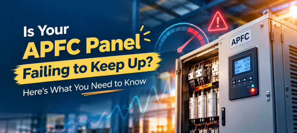
Your industrial facility is running every day. Motors are starting, machines are operating, compressors are working, and production lines are handling changing loads.
But is your APFC panel keeping up with all these changes?
An Automatic Power Factor Correction (APFC) panel helps industries maintain their power factor by automatically switching capacitor banks according to the reactive power requirement. For many industrial applications, an APFC panel can be an effective way to manage reactive power. But industrial loads do not always remain constant. When machines start and stop frequently or the reactive power demand changes quickly, a conventional APFC panel may not respond as smoothly as the load requires.
So, how does an APFC panel work? How is APFC panel capacity calculated? And when is it time to consider a more dynamic solution?
Let’s take a closer look.
How Does an APFC Panel Work?
An APFC panel automatically adjusts reactive power compensation according to the power factor of the electrical system.
The APFC panel uses a power factor controller to monitor the electrical system. When the power factor falls below the desired value, the controller switches suitable capacitor banks into the circuit. When less compensation is required, the controller disconnects the capacitor steps. The basic operation is as follows :
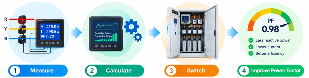
First, it measures the voltage, current, and power factor continuously. The controller then calculates the reactive power requirement and determines how much compensation is needed. Based on this calculation, the panel switches the required capacitor banks in or out automatically. This helps improve the power factor, reduce reactive power and electrical losses, and make the overall system more efficient.
How Is APFC Panel Capacity Calculated?
Selecting the right panel capacity is important for effective power factor correction. The required capacitor capacity mainly depends on the load power, existing power factor, and desired power factor.
The required reactive power compensation can be estimated using:
Qc = P × (tan φ₁ − tan φ₂)
Where:
Qc = Required capacitor capacity in kVAR
P = Active power in kW
φ₁ = Existing power factor angle
φ₂ = Desired power factor angle
The power factor angle can be obtained from:
φ = cos⁻¹(PF)
For example, consider an industrial load consuming 500 kW with an existing power factor of 0.75, and the target power factor is 0.95. The existing and target power factor angles are first calculated, and these values are then used in the formula to determine the approximate kVAR compensation required. This value helps in deciding the total capacitor bank capacity for the APFC panel. However, selecting an APFC panel is not simply about choosing a capacitor bank based on one calculation. Actual load variation, operating conditions, switching requirements, and the electrical system should also be considered.
Why Are Capacitor Steps Used in an APFC Panel?
An APFC panel normally divides its total capacitor capacity into multiple steps rather than switching one large capacitor bank at once.
For example, an APFC panel could use capacitor steps such as:
10 kVAR + 10 kVAR + 20 kVAR + 20 kVAR + 40 kVAR
The APFC controller selects different combinations of these steps according to the reactive power demand. When the load increases, additional capacitor steps are switched on. When the load decreases, unnecessary capacitor steps are switched off. This makes the panel suitable for many industrial applications where the load changes gradually.
But there is one important point.
The compensation from a conventional APFC panel is stepwise.
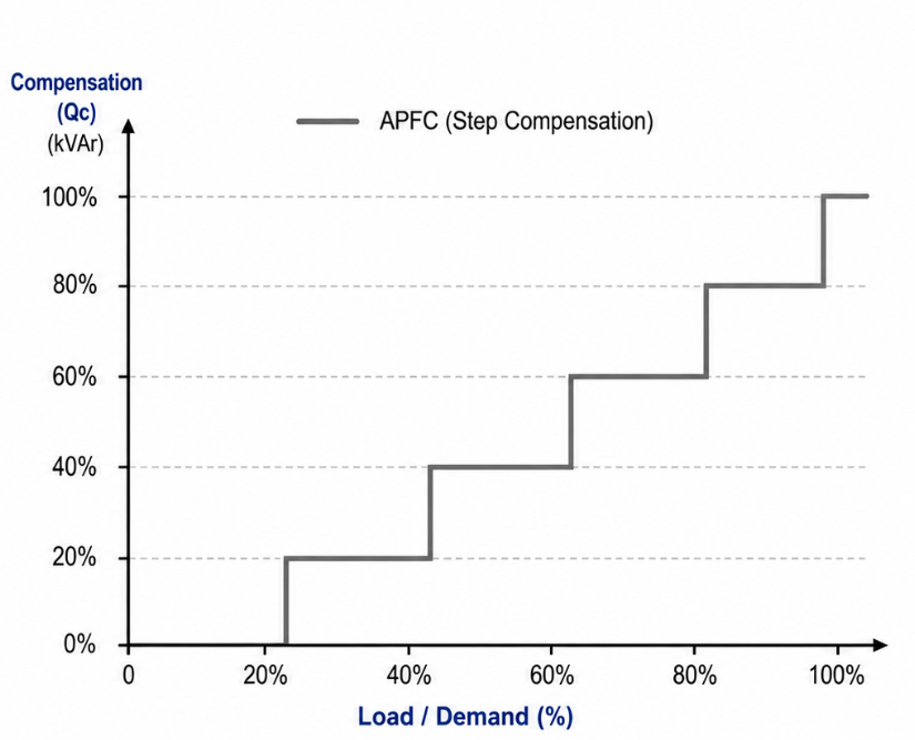
And this can become a limitation when the electrical load changes very quickly.
When Can an APFC Panel Struggle?
An APFC panel can work effectively when the electrical load is reasonably stable or changes gradually. However, modern industries often have highly variable loads. Machines may start and stop frequently, production conditions may change, and the reactive power demand can vary within a short period.
In such situations, the APFC panel has to detect the change and switch the required capacitor steps. During this process, the compensation may not exactly match the reactive power requirement at every instant. This can result in periods of undercompensation or overcompensation.
Some common signs include:
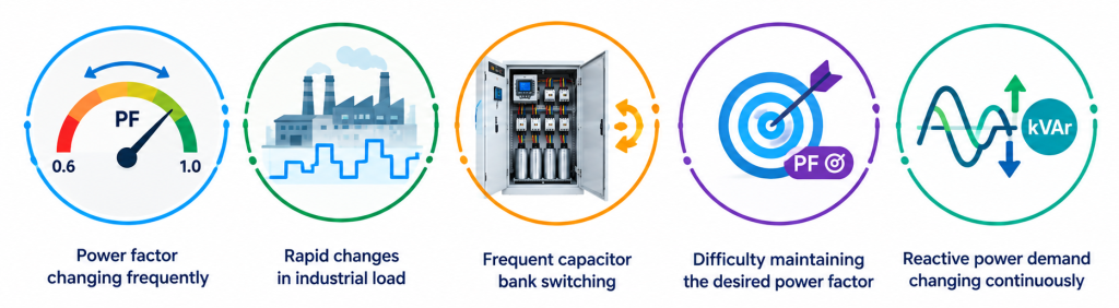
If these conditions are present, it may be worth looking beyond conventional capacitor based compensation. Industries should also consider harmonic conditions when selecting panel, with power quality requirements guided by standards such as IEEE 519.
Does Your APFC Panel Need a Faster Response?
Imagine an industrial facility where several machines operate in cycles.
One machine starts. Another machine stops. A compressor starts. Production demand changes again. With every change, the reactive power requirement can also change. A conventional panel responds by switching capacitor steps. But when these changes happen rapidly, stepwise compensation may not always provide the exact amount of reactive power required at that moment.
This is where dynamic reactive power compensation becomes important.
Instead of waiting for different capacitor steps to switch, a dynamic solution can adjust its compensation much more continuously according to the changing electrical demand.
APFC Panel vs Dynamic Reactive Power Compensation
| Feature | APFC Panel | SVG |
|---|---|---|
| Compensation method | Capacitor banks | Power electronic converter |
| Compensation | Stepwise | Continuously adjustable |
| Response | Depends on switching and controller | Very fast |
| Rapid load changes | May be less suitable | Suitable for dynamic loads |
| Reactive power control | Capacitor step based | Dynamic |
An APFC panel can remain a suitable choice for facilities with relatively stable reactive power demand. However, when the load changes rapidly and continuously, an SVG can provide faster and more flexible reactive power compensation.
What Makes an SVG Different from an APFC Panel?
A Static VAR Generator uses power electronic technology to provide dynamic reactive power compensation. Unlike an APFC panel, which switches fixed capacitor steps, an SVG can continuously adjust its reactive power output according to the changing requirements of the electrical system.
This allows the SVG to respond quickly when the load changes. For industries with rapidly changing reactive power demand, this can provide better control of power factor compared with a stepwise compensation approach.
How InPhase SVG Can Help with Dynamic Power Factor Correction
When an industrial load changes rapidly, the power factor correction system needs to respond quickly as well. The InPhase Static VAR Generator (SVG) is designed for dynamic reactive power compensation in industrial applications.
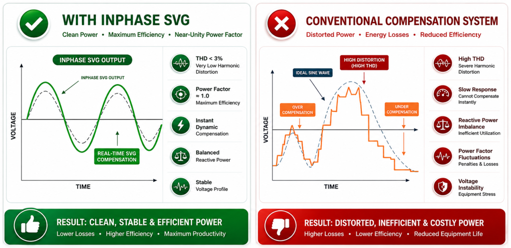
The comparison above shows how a conventional compensation system may experience over-compensation, under-compensation, power factor fluctuations, slower response, and reactive power imbalance when the load changes frequently. These limitations can make it difficult to maintain the desired power factor consistently.
The InPhase SVG addresses these challenges through fast and continuously adjustable reactive power compensation. With three-level IGBT technology, a response time of less than 0.1 ms, power factor greater than 0.99, and efficiency greater than 98%, the SVG can respond dynamically to changing load conditions. Unlike conventional capacitor-step switching, it continuously adjusts compensation according to the reactive power requirement, helping maintain a more stable power factor and reduce unnecessary electrical losses.
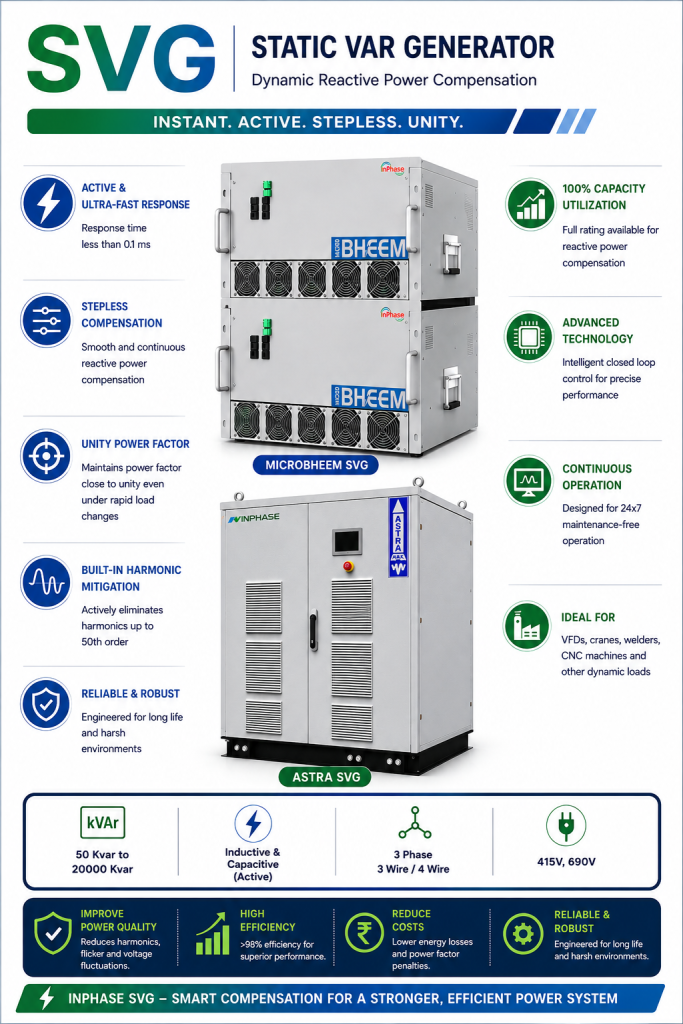
Looking for a smarter solution for dynamic power factor correction? The InPhase SVG provides fast, precise, and continuous reactive power compensation for industries with rapidly changing loads. Explore InPhase SVG solutions and take a smarter step towards stable power factor and improved electrical performance.