The brief story
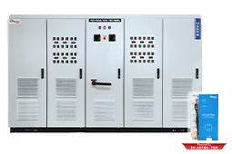
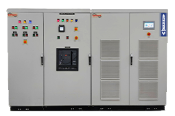
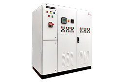
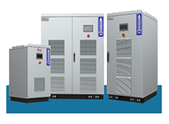
InPhase Active Harmonic Filters are an all-in-one package, capable of compensating for reactive currents, harmonic currents and unbalance currents, we claim. However, in most sites InPhase was tasked to compensate for reactive and harmonic currents alone. Then, came along a company. We will call it ‘ABC’. ABC approached us saying they had a problem of current unbalance, and that they were being threatened penalisation and disconnection of the supply by the Utility, for the same.
ABC had approached various other well-known names in the PQ industry, but none were prepared to propose a solution. And so, InPhase conducted a PQ Analysis at their site. The study results were appalling. Currents in the 3 phases read: 175A, 352A and 174A respectively.
InPhase proposed to install our beloved Active Harmonic Filter to mitigate this problem. ABC said “Go ahead, do anything. Just fix this problem for us.” And so, the InPhase Active Harmonic Filter was installed at the site.
Everybody, including us, held their breaths. “Will it work?” was the question in everyone’s minds. Then came the time, to find the answer. Annnnd Lo! The phase currents read: 52A, 50A and 51A.
Everyone’s apprehension about the InPhase Active Harmonic Filter had turned into awe. The Managing Director of ABC going to the extent of saying “Dr. InPhase has come down to save us like Lord Vishnu (Hindu god; Preserver of everything and everyone in the Universe).” Not only did the Active Harmonic Filter go on to mitigate the unbalance, it was also compensating for reactive and harmonic currents, all at the same time.
If ever there was a happy ending, this was it. 🙂
The technical explanation
The above diagram shows a delta-star step-down transformer. The outer windings represent the primary of the transformer. The windings on the inner side represent the secondary. Notice that the load is connected to the secondary across two phases only i.e. R and B.
The load forces the current direction in the secondary windings as indicated by Ir and Ib. Since the phase r and b are connected in series, Ir= Ib.
Ir and Ib are secondary currents induced from primary currents IRY and IRB. Subsequently,
IRY = IRB = I. Note also, how the direction of secondary currents differ from their corresponding primary currents.
From Kirchoff’s current law, incoming current at node R must be I+I = 2I.
The outgoing currents from node Y and B are ‘I’ each. What is observed here is that one phase carries twice the amount of current than the other two individual phases. This explains the observed readings of 175A, 352A and 174A.
It is a known fact that current has three components viz. positive sequence, negative sequence and zero sequence. Since our incoming current is through a 3-ph 3-wire system, we can ignore the zero sequence component.
Also, let us recall that both positive and negative sequence components are “balanced”, individually. It is only when they combine, unbalance occurs in the load current. Just to be on the same page, let us understand what a “balanced current” means. In a 3-ph system, is the current flowing in each phase is equal, the system is said to be balanced in simple terms.
The magnitude of unbalance is calculated in percentage.

IR=352A ; IY=175A ; IB=174A
The average current,

Therefore,

Now that the cause and magnitude of the problem were known, the next step was to mitigate it. And, to meet this objective, InPhase Active Harmonic Filter was installed.
It should be noted that the initial current readings IR=352A, IY=175A, IB=174A are a combination of reactive currents, harmonic currents and unbalance currents. And because we are concentrating exclusively on unbalance, let us take an arbitrary example to understand the same.

In the above example, the incoming currents are 100A, 100A and 40A. The underlying assumption here is that these currents are purely unbalance currents and they have no reactive or harmonic component.
InPhase Active Harmonic Filter takes feedback from 3-ph CTs. This allows the Active Harmonic Filter to measure current flowing in each line. Subsequently, this input is processed by the main controller in the equipment. The Active Harmonic Filter being an AC-DC-AC converter, can absorb and pump current from the line to the load such that the incoming current from the metering point is balanced.
The controller is capable of calculating the positive sequence component and negative sequence component from this input. Once this is calculated, it is a simple case of pumping the counteractive current to the negative sequence component, so that all that remains is the positive sequence. Recollect that positive sequence current is balanced and thus consequently, the line current is also balanced.

The above diagram is a representation of the aforementioned compensation process. Note how the line currents are balanced (80A each) whereas the load currents (100A, 100A and 40A) remain unchanged.
This way, the customer is happy that his electrical system is healthy, and the Utility is happy that the consumer’s loads are balanced and the grid is stable. Lastly, Dr. InPhase is also happy that he made it all possible. 🙂
It is time now, for you to experience the InPhase Active Harmonic Filter. Get in touch with us, we’ll help you to get your Power Quality problems resolved.
Thank you!

Thanks for reading…if you have questions don’t forget to ask me. You could write to me to info@inphase.in or call +919632421402

InPhase Power is a Power Electronic Product company manufacturing products for Power Quality and Power Conversion. InPhase is manufacturer of Active Filter, Active Harmonic Filter, Solar Inverter. InPhase majors in power system design for power quality and conversion. Driven by a management that has a combined experience of over 60 years in power system and power electronics InPhase nurtures innovation and passion in this field.

