

The ever increasing load complexity
At first, consider the load to be purely resistive; a simple incandescent lamp maybe, just to make things more “real” (pun intended). In such a case, only real power will be drawn from the grid. Just when things are going smooth, we decide to connect an induction motor at the load end. But, the induction motor requires an excitation current in the field coils for its desired operation. Hence, drawing pure real current from the grid is no more sufficient. Therefore, in addition to the real power, a new component, namely reactive power is drawn from the grid.
As our next step in this experiment, we introduce a new “problem” in our setup. We deliberately rearrange our loads such that they are not balanced, i.e. the current drawn in the three individual phases are not equal. In technical terms we call this phenomenon, load unbalance. Just for representation, it is shown as if unbalance is a new component being drawn from the grid. In reality, however, unbalance is a “phenomenon” and not a “component”. The idea of this representation will be disclosed in the following lines.
Just as we might begin to think that things couldn’t get any worse, drives-based motor control system is introduced! This power electronic marvel starts functioning; and consequently introduces harmonics in our power system. Therefore at this point in time, our power system suffers from the following problems – low power factor, load unbalance and harmonics.
The solution
Now that all possible problems have arisen in the system, it is time to introduce the hero – the Active Filter. For the sake of representation, let us assume that the Active Filters kills the problems one-by-one. Starting with reactive power, it is seen that the reactive power being imported from the transformer is compensated by a counter-acting power from the Active Filter. In an alternate view, it can also be seen as if the reactive power requirement of the load is fed by the Active Filter. Unbalance in a system can be attributed to presence of negative sequence components and zero sequence components of currents. Active filter is capable of eliminating the negative sequence and zero sequence components from the electrical system, as shown. Here is a case study on Unbalance Compensation if you want to learn more about it. Subsequently, on elimination of unbalance, harmonics is the only problem left to be solved in the system.
The Active Filter senses the current from the CTs connected within the plant. With this input, the controller present in the Active Filter catches the harmonic content and pumps the same current in anti-phase. In this manner the harmonics are cancelled out in the system.
We hope that this article answers, in brief, the million dollar question of “How exactly does an Active Filter work?” Thank you for reading and hope to see you soon with a new article!
Meet you again with a interesting article, until then bye from Dr.InPhase
Thank you!

Thanks for reading…if you have questions don’t forget to ask me. You could write to me to info@inphase.in or call +91 9632421402

InPhase Power is a Power Electronic Product company manufacturing products for Power Quality and Power Conversion. InPhase is manufacturer of Active Filter, Active Harmonic Filter, Solar Inverter. InPhase majors in power system design for power quality and conversion. Driven by a management that has a combined experience of over 60 years in power system and power electronics InPhase nurtures innovation and passion in this field.

 Power Factor Improvement
 KVAH Billing Reduction
 Captive Power PF Improvement
 Harmonics Mitigation
 Drives Harmonic Mitigation
 Unbalance Compensation
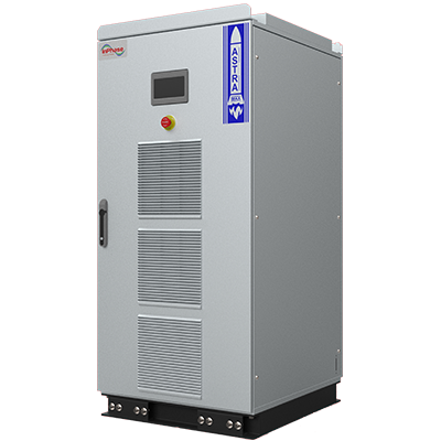 Active Harmonic Filter
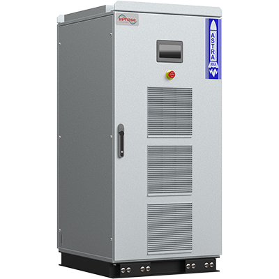 Static VAR Generator
 Modular AHF
 Modular SVG
 Smart Hybrid Active Filter
 APFC
APFC RTPFC
RTPFC Power Quality Study
 Energy Audit
 Harmonics Analysis
 Product Support


