
Modern industrial facilities operate in a highly dynamic electrical environment. Power quality, once a secondary consideration, has become a critical operational parameter that directly impacts plant uptime, equipment lifespan, and utility billing. Reactive power management is at the core of power quality optimization.
Historically, industrial loads required simple inductive reactive power compensation, which was adequately addressed by conventional Automatic Power Factor Correction (APFC) panels. However, the proliferation of non-linear loads, high-speed switching devices, and complex automation systems has fundamentally altered facility electrical profiles. This article explores the technical transition from traditional APFC systems to Smart Hybrid Compensation technologies, detailing the engineering principles, standard compliance, and practical application strategies for modern industrial networks.
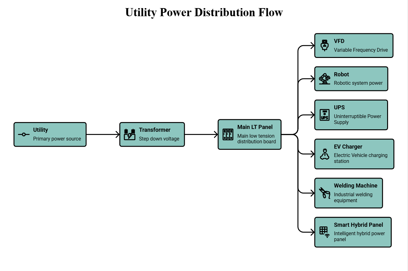
Why Traditional APFC Served Industries for Decades
Before examining the need for advanced compensation, it is essential to understand why conventional APFC systems were the standard for industrial reactive power management for over half a century.
Traditional industrial processes relied heavily on direct-on-line (DOL) induction motors, standard synchronous machines, and resistive heating elements. These loads exhibited highly predictable electrical behavior:
Stable Industrial Loads: Load variations occurred gradually. Motors ran continuously for hours or days, resulting in a steady-state reactive power profile.
Traditional Induction Motors: The primary source of low power factor was the magnetizing current required by standard AC motors. This lagging reactive power requirement was linear and easily quantifiable.
Lower Harmonic Levels: Early industrial environments utilized minimal power electronics. Consequently, the Total Harmonic Distortion (THD) in both voltage and current was negligible, eliminating the risk of complex resonance issues.
Fixed Reactive Power Demand: The reactive power demand changed only when large load blocks were manually switched on or off.
The fundamental reactive power equation defines this relationship:
Where:
Q = Reactive power (kVAR)
P = Active power (kW)
tanϕ = Phase angle between voltage and current
Traditional APFC systems were designed explicitly to compensate this predictable, slowly changing reactive demand (Q) by switching large capacitor banks in discrete mechanical steps. Because conditions were stable, this method was highly effective, economical, and robust.
Limitations of Conventional APFC
While traditional APFC systems are cost-effective for stable, linear environments, they present significant technical limitations when applied to modern, dynamic electrical networks.
Step-Resolution Limitations: Conventional APFCs operate in discrete steps (e.g., 50 kVAR). If a load requires a fraction of a step, the system either under-compensates or over-compensates, resulting in a leading power factor and dangerous voltage rises.
Electromechanical Wear and Tear: Contactor-switched systems are subject to mechanical degradation and electrical arcing during switching operations, requiring frequent maintenance.
Inability to Handle Fast Transients: For rapid loads like stamping presses or cranes, the reactive power demand peaks and vanishes before the electromechanical APFC can respond.
Capacitor Switching Transients: Switching large, uncharged capacitor banks directly onto the bus creates severe inrush currents, degrading sensitive electronics upstream.
Modern Industrial Loads and New Challenges
The transition to Industry 4.0 has introduced advanced power electronics into almost every aspect of facility operation.
Loads are no longer linear or steady. Variable Frequency Drives (VFDs), sophisticated robotics, arc furnaces, and LED lighting networks introduce two primary challenges:
High-Speed Load Fluctuations: Automated welding and robotics generate highly dynamic reactive power demands that fluctuate in milliseconds.
Non-Linear Current Draw: Power electronic converters draw current in short, abrupt pulses rather than smooth sinusoidal waves.
These non-linear current pulses distort the fundamental 50/60 Hz waveform, injecting harmonic currents back into the facility’s electrical distribution system.
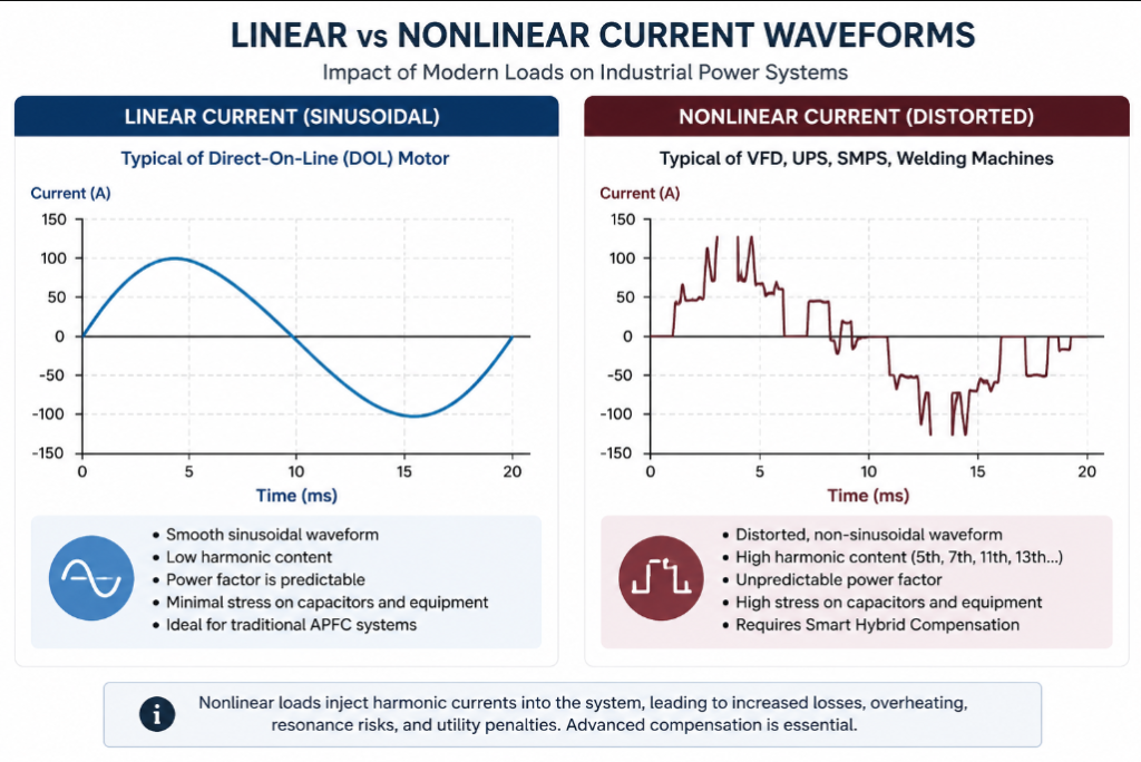
Harmonics and Resonance
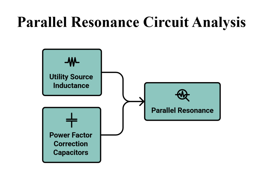
When non-linear loads inject harmonic currents into the power system, they interact with the source impedance and any connected capacitance. Capacitors present a lower impedance to higher frequencies, acting as a sink for high-frequency harmonic currents, leading to premature dielectric failure.
More critically, the combination of utility source inductance (Ls) and power factor correction capacitance (C) creates a parallel resonant circuit. The parallel resonance frequency (fr) is calculated as:
If the calculated resonance frequency aligns with a harmonic order generated by the facility’s loads (typically 5th, 7th, 11th, or 13th), harmonic resonance occurs. This amplifies harmonic currents by a factor of 10 to 15. To mitigate this, detuned reactors must be placed in series with the capacitors.
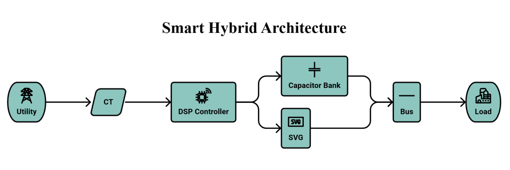
Understanding Smart Hybrid Compensation
Smart Hybrid Compensation systems resolve the conflicting requirements of bulk reactive power support and dynamic, high-speed harmonic mitigation. They combine Passive Compensation (detuned capacitor steps) for base-load support and Active Compensation (Static Var Generator – SVG) for step-less tuning.
Advanced Control and Monitoring Capability The true advantage of a hybrid system lies in its control architecture. Modern systems utilize advanced Digital Signal Processor (DSP) control running in a strict closed-loop operation.
Real-Time Compensation: The DSP continuously monitors the load profile via current transformers, running adaptive algorithms that instantly calculate the required reactive and harmonic current vectors.
Harmonic Detection: Advanced Fast Fourier Transform (FFT) algorithms isolate individual harmonic orders, allowing the active module to inject precise cancellation currents.
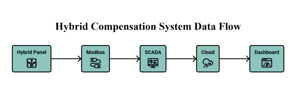
Industrial Connectivity: Facility managers can seamlessly integrate these panels into plant-wide SCADA systems using Modbus RTU/TCP communication.
Modern Power Electronics Technology
The active portion of a hybrid system relies on sophisticated solid-state technology.
Three-Level IGBT Topology
Modern SVGs and Active Harmonic Filters utilize a three-level Neutral Point Clamped (NPC) IGBT topology rather than traditional two-level inverters. This provides critical engineering advantages:
-
Reduced Switching Losses: Distributing the voltage stress across more devices drastically lowers thermal losses.
-
Better Waveform Quality: Three-level switching produces a stair-step voltage waveform that much more closely approximates a pure sine wave.
-
Lower dv/dt Stress: The reduced voltage steps minimize the rate of voltage change (dv/dt), protecting downstream insulation and reducing stress on the facility grid.
LCL Output Filters
To interface the high-speed switching IGBTs with the facility grid safely, the inverter output is passed through an LCL (Inductor-Capacitor-Inductor) filter network.
-
Purpose of LCL Filters: The LCL filter acts as a highly effective low-pass filter, trapping the high-frequency ripple generated by the IGBTs.
-
Improved Current Quality: It provides superior high-frequency attenuation compared to simple L-filters, resulting in a cleaner grid connection and improved inverter output performance.
-
Reduced Electromagnetic Interference (EMI): By trapping high-frequency switching noise (typically 10 kHz to 20 kHz), the LCL filter prevents EMI from propagating through the plant, protecting sensitive communication networks and PLCs.
Worked Engineering Examples
Engineering Example 1: Sizing Total Reactive Power Compensation
Given Data: Real Power (P): 1200 kW, Existing PF (cos φ1): 0.78, Target PF (cos φ2): 0.98.
Calculation:
Qc = P(tanφ1 − tanφ2)
Qc = 1200 × (tan 38.74° − tan 11.48°)
Qc = 1200 × (0.802 − 0.203)
Qc = 718.8 kVAR
Engineering Example 2: Resonance Calculation and Detuning
Given Data: Transformer: 2000 kVA (Z% = 6%), Cap Bank: 500 kVAR, f1: 50 Hz.
Calculation: Short circuit capacity Ssc = 33333 kVA
fr = 50 × √(33333/500)
fr = 408 Hz
Solution: 408 Hz is dangerously close to the 7th harmonic (350 Hz). A 7% detuning reactor shifts the tuning frequency to 189 Hz, safely below the 5th harmonic (250 Hz).
Engineering Example 3: The Limitation of Step Compensation
Objective: Demonstrate how traditional APFC fails with fractional loads and how Hybrid systems resolve it.
Given Data:
Dynamic Load Reactive Demand: 37 kVAR (Lagging)
APFC Minimum Step Size: 50 kVAR
Scenario A: Traditional APFC Operation
The controller detects a 37 kVAR demand. To avoid under-compensation penalties, it switches on a 50 kVAR step.
Net Reactive Power: 37 kVAR (Load) – 50 kVAR (Capacitor)} = -13 kVAR
Result: The system is overcompensated by 13 kVAR. This leading power factor causes unnecessary terminal voltage rise and potential utility penalties for leading kVARh. The controller may repeatedly switch this step on and off (hunting), causing severe mechanical wear.
Scenario B: Smart Hybrid Operation (SVG + Passive)
The hybrid DSP detects the 37 kVAR demand.
The system leaves the 50 kVAR passive step OFF.
The active SVG module instantaneously injects exactly 37 kVAR.
Alternatively: If the 50 kVAR passive step was already ON, the SVG will actively absorb 13 kVAR of inductive reactive power, perfectly balancing the bus to 0 kVAR.
Result: Perfect unity power factor, zero voltage swell, and zero unnecessary contactor switching.
Standards and Compliance
Industrial power quality is governed by strict international standards:
IEEE 519: Specifies limits for voltage and current harmonics at the Point of Common Coupling (PCC). Active compensation directly reduces Total Demand Distortion (TDD) to compliant levels, preventing utility penalties.
IEC 60831: Pertains to self-healing shunt power capacitors.
IEC 61921: Outlines requirements for low-voltage power factor correction banks.
IEC 61000 Series: Covers Electromagnetic Compatibility (EMC). High-speed IGBT switching in hybrid systems must be carefully filtered (via LCL filters) to prevent EMI.
Response Time Comparison
When evaluating compensation, engineers must clearly distinguish between controller response (how fast the DSP calculates the math), compensation response (how fast the hardware actuates), and system response (how long it takes the entire network to reach steady-state correction).
| Technology | Controller | Compensation | Total Response |
|---|---|---|---|
| Contactor APFC | ~100 ms | 1–5 s | 5–60 s |
| Thyristor APFC | ~20 ms | 10–20 ms | 20–40 ms |
| Active SVG | <100 μs | <1 ms | <5 ms |
| Smart Hybrid | <100 μs | <1 ms (active part) | <5–15 ms |
ROI and Commercial Benefits
Engineering solutions must justify their capital expenditure. Moving to a Smart Hybrid system yields a calculable ROI across multiple operational metrics.
Generalized Industrial Case Study
A heavy manufacturing plant utilizing large stamping presses and automated spot welding lines experienced consistent utility penalties due to poor power factor, as legacy APFCs could not track sub-second welding cycles.
Intervention: The plant replaced the legacy APFC with a 1000 kVAR Smart Hybrid System.
kVAh Billing Optimization: By maintaining a unity power factor under dynamic conditions, utility penalties were eliminated.
I²R Loss Reduction: Compensating reactive current locally reduces total line current, reducing copper heating losses.
Operational Uptime: Active voltage stabilization mitigated localized voltage sags during welding. CNC machine fault rates dropped to zero.
Lifecycle Cost Reduction
Beyond immediate utility bill savings, transitioning to hybrid architecture drastically reduces Operational Expenditure over the equipment’s 10-to-15-year lifecycle. Benefits include:
Reduced Capacitor Replacement Costs: Detuning and active harmonic cancellation prevent dielectric degradation.
Eliminated Contactor Replacements: Solid-state active support severely reduces the mechanical duty cycle of traditional contactors.
Lower Maintenance Manpower: Reduced panel maintenance requirements free up engineering staff.
Lower Inventory of Spare Parts: Fewer mechanical failures mean fewer required spares in the facility stockroom.
Extended Equipment Life: Stabilized voltage profiles and reduced harmonic heating extend the operational life of facility transformers and downstream drives.
APFC vs Smart Hybrid Comparison
| Parameter | APFC / TSC (Passive) | SMART HYBRID |
|---|---|---|
| Reactive Power Compensation | Stepped Reactive Power Compensation | Stepless Reactive Power Compensation |
| Compensation Accuracy | Over Compensation / Under Compensation | No Over / Under Compensation |
| Reactive Power Demand | Fixed Step Compensation | Dynamic (Stepless) Fast Reactive Power Compensation |
| Switching | Frequent Thyristor / Contactor Switching Reduces Life | Capacitor Units Controlled Smartly and No Frequent Switching |
| Cost / Solution | Low Cost but Poor Performance | Value Engineered Solution |
| Efficiency | Poor Efficiency | High Efficiency |
| Compensation Type | Only Lagging Compensation | Both Lagging and Leading Compensation |
| Response Time | Poor Response Time | High Speed Instant Response (Milliseconds) |
| Over / Under Compensation | Frequent Over Compensation / Under Compensation | No Chances of Over Compensation / Under Compensation |
| Space Requirement | Occupies Lots of Space | Very Compact |
| Functionality | Manages Only Power Factor | Can Manage Power Factor and Harmonics Simultaneously |
The InPhase Approach
The InPhase approach to power quality relies on several core engineering principles:
Intelligent Combination: Pairing high-capacity detuned passive networks with fast-acting solid-state active modules manages both bulk demand and volatile transients efficiently.
Dynamic Reactive Power Support: Sub-cycle responses fill the gaps left by passive steps, ensuring a perfectly flat reactive power draw.
Harmonic Management First: Natively monitoring and addressing harmonic spectrums prevents localized resonance.
Reduced Switching Operations: Prioritizing the active module for minor load variations significantly reduces the mechanical duty cycle of the passive contactors.
Real-Time Visibility and Digital Monitoring
Modern power quality management requires robust data. The InPhase architecture transforms the compensation panel from a reactive component into a proactive digital node:
Comprehensive Monitoring: Provides real-time visibility into voltage and current THD, facility power factor, and live compensation current.
Event Logging & Trends: Captures historical load trends and event logs, enabling engineers to perform precise root-cause analysis of electrical anomalies.
Predictive Maintenance: Digital oversight tracks component duty cycles and thermal profiles, facilitating predictive maintenance that flags issues before catastrophic failures occur.
Remote Diagnostics: Allows off-site power quality experts to evaluate grid health and adjust tuning parameters dynamically.
Industry 4.0 Integration: Full Modbus support guarantees that all electrical data flows seamlessly into broader plant SCADA and energy management platforms.
Future Trends
The landscape of industrial power systems is moving rapidly toward digitalization. Facility engineers should prepare for several practical emerging trends:
Industrial IoT and Industry 4.0 Integration: Compensation panels are transitioning from standalone hardware to integrated nodes on the factory network, feeding real-time power quality data directly to central SCADA systems.
Predictive Maintenance: Advanced DSP controllers now track contactor duty cycles, temperature profiles, and capacitor degradation, alerting engineers to replace components before a catastrophic failure occurs.
Remote Diagnostics: Cloud-enabled condition monitoring allows power quality experts to dial into facility panels remotely, analyzing waveform captures and adjusting tuning parameters without requiring on-site visits.
Digital Monitoring: Granular tracking of power quality metrics down to the machine level will become standard, directly linking electrical efficiency to production KPIs.
Conclusion
The shift from conventional Automatic Power Factor Correction to Smart Hybrid Compensation is an engineering necessity dictated by the changing nature of industrial loads. While legacy APFC systems served the predictable, linear facilities of the past adequately, the modern automated plant requires a more sophisticated approach.
By integrating robust passive networks with ultra-fast active power electronics, facility managers can effectively neutralize harmonic distortion, eliminate utility penalties, and protect sensitive automation equipment. For industries prioritizing continuous uptime and electrical efficiency, upgrading to smart hybrid architecture represents a critical investment in long-term operational stability.