
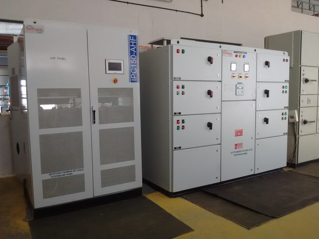
Active Harmonic Filter Working Principles is one of the most important concepts in modern power quality engineering. As industries increasingly adopt Variable Frequency Drives (VFDs), UPS systems, rectifiers, induction furnaces, robotics, and renewable energy converters, harmonic distortion has become a major challenge affecting electrical system performance.
Unlike conventional passive filters that eliminate only specific harmonic frequencies, an Active Harmonic Filter (AHF) continuously detects harmonic currents and injects equal and opposite compensation currents in real time. This intelligent compensation improves power quality, reduces Total Harmonic Distortion (THD), increases equipment life, and ensures compliance with IEEE 519.
Why Harmonics Occur
Modern nonlinear loads draw current in pulses rather than smooth sinusoidal waveforms.
Examples include
- Variable Frequency Drives
- UPS Systems
- Rectifiers
- EV Chargers
- CNC Machines
- Arc Furnaces
The distorted current can be represented as
i(t) = I1 sin(ωt) +
Σn=2∞
In sin(nωt + φn)
Where:
- I1 = Fundamental current (50 Hz or 60 Hz component)
- In = RMS value of the nth harmonic current
- n = Harmonic order (typically 3, 5, 7, 11, 13, …)
Total Harmonic Distortion
THD is calculated as
THDI =
√(
I22 +
I32 + …
+ In2)
/
I1
× 100%
According to IEEE-519
| THD | Condition |
|---|---|
| <5% | Excellent |
| 5–8% | Acceptable |
| >8% | Poor |
Active Harmonic Filter Working Principles
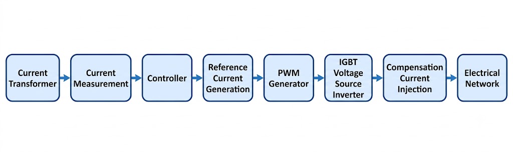
The Active Harmonic Filter Working Principle consists of four major stages.
Step 1 – Current Measurement
Current Transformers continuously measure the load current.
iL = if + ih
- Fundamental Current
- Harmonic Current
- Reactive Current
Step 2 – Harmonic Detection
A Digital Signal Processor extracts
- Fundamental component
- Harmonic component
- Reactive component
Using
- FFT
- dq Transformation
- Instantaneous p-q Theory
- Synchronous Reference Frame (SRF)
the controller determines
ic = – ih
Step 3 – Reference Current Generation
The controller generates the compensation current
where ic* is the reference current for the inverter.
Step 4 – Current Injection
The PWM inverter injects the compensation current into the electrical system: ic(t)
The source current becomes:
After harmonic compensation:
Only the fundamental current remains, resulting in a nearly sinusoidal source current with significantly reduced harmonic distortion.
Mathematical Principle
The load current can be expressed as:
Where:
- if = Fundamental current
- ih = Harmonic current
The Active Harmonic Filter injects a compensation current equal in magnitude and opposite in phase to the harmonic current:
Therefore, the source current becomes:
Substituting the expressions for load and compensation currents:
Hence,
Only the fundamental current remains in the source current after compensation, while the harmonic currents are effectively cancelled by the Active Harmonic Filter. Only the fundamental current remains.
Harmonic Compensation Equation
The harmonic current required is:
IAHF =
√(
I22 +
I32 +
··· +
In2
)
The minimum Active Harmonic Filter (AHF) rating becomes:
RatingAHF =
√3 ×
VL
×
IAHF
×
Safety Factor
Reactive Power Compensation
The inverter also supplies reactive current:
Power Factor
After compensation:
As the Active Harmonic Filter (AHF) compensates harmonic and reactive currents in real time, the source current becomes nearly sinusoidal, the power factor approaches unity (PF ≈ 1), and the electrical system operates with improved efficiency, reduced losses, and compliance with IEEE 519 power quality standards.
Advantages
- Real-time harmonic compensation
- THD below 5%
- Dynamic reactive power compensation
- Load balancing
- Neutral current reduction
- Fast response (<20 ms)
- IEEE 519 compliance
- Reduced transformer heating
- Lower maintenance costs
- Improved energy efficiency
Industrial Applications
- Steel Plants
- Cement Plants
- Pharmaceutical Industries
- Textile Mills
- Data Centers
- Commercial Buildings
- EV Charging Stations
- Hospitals
- Airports
- Water Treatment Plants
Comparison
| Feature | Passive Filter | Active Harmonic Filter |
|---|---|---|
| Dynamic Compensation | ✗ | ✓ |
| Harmonic Order | Fixed | Multiple |
| Resonance Risk | High | None |
| Power Factor Correction | Limited | Excellent |
| Load Adaptability | Poor | Excellent |
| IEEE 519 Compliance | Difficult | Easy |
InPhase Active Harmonic filter
The Active Harmonic Filter Working Principles implemented in the InPhase Active Harmonic Filter (AHF) is based on real-time harmonic detection and compensation. Using advanced DSP-based digital signal processing, the system continuously monitors load currents, identifies harmonic components generated by non-linear loads, and instantly injects equal and opposite compensation currents into the electrical network. This Active Harmonic Filter Working Principle effectively cancels harmonic distortion, improves power factor, and restores a nearly sinusoidal source current.
Unlike conventional passive filters that eliminate only selected harmonic frequencies, the InPhase Active Harmonic Filter Working Principles enables dynamic compensation across multiple harmonic orders without creating resonance. The system also provides reactive power compensation, load balancing, and neutral current reduction, making it an ideal solution for modern industrial electrical systems with rapidly changing load conditions.
Key Features Based on the Active Harmonic Filter Working Principles
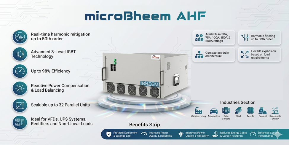
- Real-time harmonic compensation up to the 50th harmonic order
- High-speed DSP controller implementing the Active Harmonic Filter Working Principles
- Total Harmonic Distortion (THD) reduced to below 5%
- Dynamic reactive power compensation and power factor correction
- Response time of less than 20 milliseconds
- Automatic load balancing and neutral current compensation
- Modular, scalable, and retrofit-friendly architecture
- Compliance with IEEE 519 power quality standards
- Intelligent monitoring through HMI, Modbus RTU, Modbus TCP/IP, and Ethernet communication
- High operating efficiency exceeding 98%